Understanding Density In Particle Rendering Mode
Introduction
Krakatoa is a volumetric renderer, it is normally not used to shade thin surfaces like most other renderers for 3ds Max, and of course this results in a different workflow.
It is important to keep this in mind when attempting to shade surfaces made of particles - when all particles are more or less co-planar without any particle cloud thickness - the lighting and self-shadowing algorithm can produce artifacts similar to the moire effects you would get if rendering polygons with shadow maps and a Bias of 0.0. In that case, the polygons would be exactly at the interface between light and shadow and only the numeric precision of the software would decide whether a point will be seen as lit or in shadow - theoretically, a point at the border between light and shadow is in neither, but practically the renderer has to pick a side, and it picks it after a certain numeric pattern, which results in the regular pattern seen on the surface.
When a particle cloud has thickness, light is attenuated when passing through particles based on their density. This causes less light to reach particles that are behind the other particles, then the light is attenuated again and after a certain depth inside the volume, it can be completely extinguished. The result is a nice sub-surface light bleeding which is typically desirable because that is how light behaves in the real world when penetrating particulate matter like dust clouds or smoke. In the current version of Krakatoa, the light is not being scattered within the cloud though, it travels in one direction based on the light source type.
The Density of a single particle can be affected by multiple factors. Normally, a particle starts with a density of 1.0, or if loaded from a PRT File, with the density that was saved into the file. That density can then be affected by:
- the Node’s Visibility Track (usually between 0.0 and 1.0);
- the Material Opacity (unless using Krakatoa Material with Multiply Density unchecked)
- the Global Particle Density factor in the Krakatoa GUI which can be the same or different for the Lighting and the Final pass;
- the Shadow Density parameter in Lights when calculating the Lighting pass.
Note that the rendered image / shadow map resolution plays a role when determining the density - Krakatoa draws each particle as a single pixel, thus rendering at higher resolutions can cause a particle cloud to appear less dense, and zooming out in the same scene can make the same cloud appear more dense. This is somewhat consistent with the way particulate matter would appear in the real world - if you move inside a sand storm, you would see single particles flying around you and lots of gaps between them, looking at the same cloud from a large distance would make it appear more or less solid.
Shading Surfaces as Particles and Fighting the Moire Patterns
The Problem
The following simple example uses a Geosphere with 10 segments and a Particle Flow distributing 1 million particles on the surface without any offset. A direct light is illuminating the sphere.
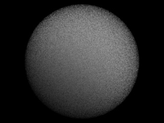
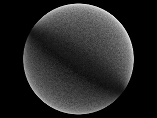
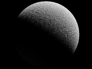
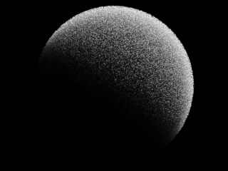
The next image was rendered with the default density of 5.0 * 10^-1 (values of 5.0 and -1 in the Krakatoa GUI, which represents 0.5):
As expected, this produces a very pronounced moire effect caused by self-shadowing particles at the border between light and darkness. The surface of the particle cloud facing the light source is shaded really dark because the particles on the surface are too dense (attenuating the light a lot) and at the same time often fall in their own shadow and receive no light at all.
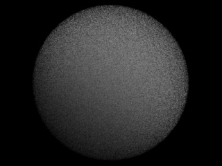
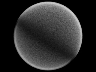
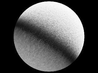
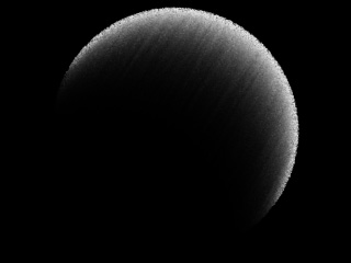
Reducing the Density by an order of magnitude down to 0.05 reduces the effect but does not fix the problem completely - because the particles are less dense, their shadow is also less dense. Thus, the light is not extinguished completely and even particles that fall in their own shadow get the remaining portion of it:
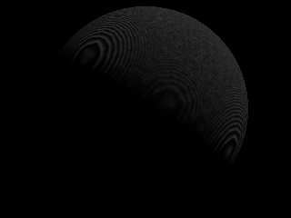
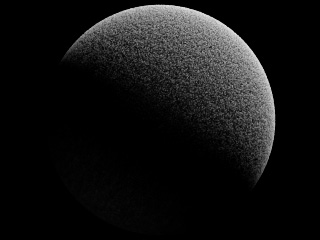
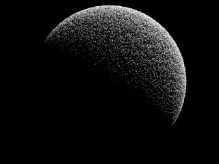
Reducing the Density once again down to 0.005 removes the moire pattern, but this is at cost of no shadow casting from the upper right particles onto the bottom left particles - the backside of the sphere is lit almost identically to the side facing the light because the density is too low and light can pass through the particles without much attenuation:
The Solution
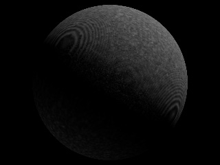
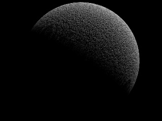
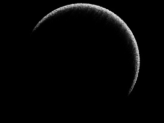
Instead of creating all particles at the same surface without providing the particle cloud with any thickness, let’s add an offset to the particles relatively to the surface - in the Particle Flow > Position Object operator, there is an Offset option. Using the default -1/1 values, let’s render at density of 0.005 again:
In this case, the light still penetrates the complete sphere, but there is a visible thickness to the particle “shell”. Thus, increasing the particle density to 0.05 leads to a rather pleasant result:
Going even higher to a density of 0.5 does not improve the result - the light is attenuated within the very top of the particle cloud and some artefacts can start appearing at the sides again:
So at a render resolution of 320x240 and 1M particles with 0.05 particle density, we have an acceptable result.
Controlling Lighting Pass Density Separately
The Krakatoa GUI allows you to specify different density for the attenuation calculations and for the final pass rendering.
The following is the result of calculating the Lighting pass using a density of 0.05 while drawing the Final pass using a density of 0.5 - the shadows will be less dense, while the particles will still be rendered as relatively opaque. It combines the “hardness” of the surface appearance shown by the Density of 0.5 in the above example while retaining the illumination intensity of the 0.05 density example:
Using even less density for the Lighting pass causes more light to leak through the surface and illuminate the back side of the sphere, while still shading as a rather dense point cloud:
A similar effect can be achieved by keeping the global density to 0.5 for both passes by reducing the Shadow Density value in the light - this allows for per-light tweaking of shadow / light attenuation calculations in Krakatoa.
Light Attenuation In Solid Volumes
Let’s take a look at the light attenuation within a full sphere of one million particles. Instead of using the Geosphere’s volume as emitter which can take a very long time to calculate in Particle Flow, we can add a Position Icon operator and switch the PFlow Emitter to Sphere shape with the same radius and position as the Geosphere.
The left image shows the result of rendering the full spherical volume with density of 0.5. Using the Near Clipping Plane to remove the front half of the particle volume, we can see how the light penetrates the surface of the cloud and becomes extinct after a rather short distance in the right image:
Decreasing the Density to 0.05 results in the following images:
Decreasing the Density even more to 0.005 causes the light to penetrate the whole volume with very little extinction: