Particle Rendering Mode
Available in Krakatoa v1.0.0 and higher
Overview
- Particle rendering is the original rendering mode of Krakatoa where each particle is considered a point with the size of a pixel.
- After the particle data is loaded, the particles are sorted for each light and illuminated and after being sorted relatively to the camera, they are drawn into the image buffer one by one back to front, blending with the already drawn particles according to the Density value and the Filter Mode / Pixel Coverage.
Filter Modes
- The Filter Mode defines how the particle data is accumulated into the pixels of the image buffer.
- The particles are sorted and drawn in order by distance to the camera or light source, so they either blend with the already drawn particles when rendering volumetrically, are added to the existing pixels when fully additive, or a mixture of both depending on their Emission, Absorption and Scatter Color values.
- While a particle is considered a pixel-sized point, the actual number of pixels drawn by Krakatoa depends on the “Draw Point Filter” mode specified in the Final Pass settings of the Main Controls rollout.
- Currently there are three Filter modes:
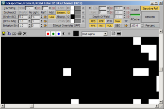
Nearest
- The particle will be drawn into exactly one pixel, the one that is closest to the actual position of the particle in image space.
- In other words, if the position of the particle is between the actual pixels, only the pixel that has the largest coverage by the particle will be filled with the full color and density.
- In the image below, you can see an extreme zoom of the 3ds Max Rendered Image Window centering on a single particle rendered with Nearest filtering:
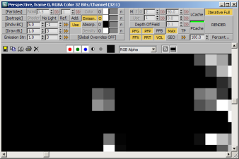
Bilinear
- This is the factory default mode for final rendering.
- Until Krakatoa MX v2.0.0, the filter had a fixed sample size of 1. For details on rendering with Bilinear Filter Sample Size higher than 1, please see this topic.
- When the filter size is 1, the particle will be drawn into a 2x2 pixels square using Bi-linear interpolation.
- Each pixel will typically receive a different color and alpha value depending on the particle coverage.
- In the image below, you can see an extreme zoom of the 3ds Max Rendered Image Window centering on a single particle rendered with Bilinear filtering:
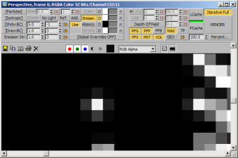
Bicubic
- Each particle will be drawn into a 3x3 pixels square using Bi-cubic interpolation.
- Each of the 9 pixels will typically receive a different color and alpha value depending on the particle coverage.
- In the image below, you can see an extreme zoom of the 3ds Max Rendered Image Window centering on a single particle rendered with Bicubic filtering:
Filter Modes and Render Elements Output
- The filter mode (see above) also affects the way Render Elements are accumulated.
- Render Elements generally collect data other than the Color values of the particles and represent it as RGB values, while using the same Alpha as the main RGBA output.
- Render Elements have their own “Enable Filtering” option which controls whether the pixels will apply the Bi-linear or Bi-cubic interpolation or will fill all pixels with the same value.
- The Render Elements typically represent data of only the particles closest to the camera, in other words each particle is supposed to overwrite any pixels it covers, thus removing data already written by particles farther to the camera.
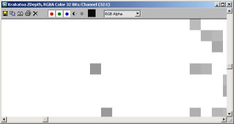
Render Element And Nearest Filtering
- When the “Draw Point Filter” drop-down list in the Main Controls rollout of the Krakatoa GUI is set to “Nearest”, the Render Elements will ALWAYS draw into the nearest pixel, disregarding the state of the “Enable Filtering” option of the Render Element.
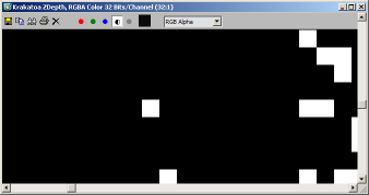
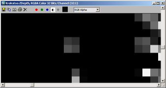
- Below is the output of the Krakatoa ZDepth Render Element with “Use Depth Range” enabled and set to Min. 0.0 and Max. 200.0, thus normalizing the color output between 0 (near) and 1 (far)
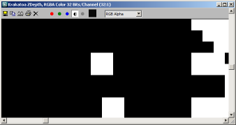
- The left image shows the RGB values, the right image shows the Alpha which is identical to the Alpha of the main output shown earlier on this page:
Render Elements And Bilinear Filtering
- When the “Draw Point Filter” drop-down list in the Main Controls rollout of the Krakatoa GUI is set to “Bilinear”, the Render Elements will draw differently depending on the state of the “Enable Filtering” option:
- In the case of Krakatoa ZDepth, the Render Element will be set to “Enable Filtering” unchecked by default because a filtered (anti-aliased) Z-Depth buffer makes no sense - the color is supposed to represent a distance and any change to the color due to filtering will skew this information.
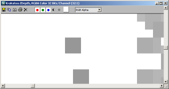
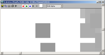
- The following images show the RGB and Alpha outputs of the Krakatoa ZDepth Render Element rendered with Bilinear filtering and “Enable Filtering” off - the 2x2 pixels square is filled with the same distance value because the particle is covering all 4 pixels somewhat:
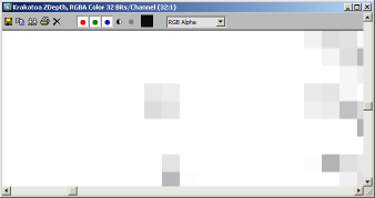
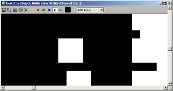
- Just for illustration purposes, enabling the Render Element’s filtering produces the following output which is meaningless as a depth information carrier:
Render Elements And Bicubic Filtering
- The same rules as described above apply to the Bicubic filtering mode, except for the pixel square being 3x3 pixels:
- Obviously, a particle closer to the camera will overwrite 9 pixels that might be already filled by other particles farther away even if its coverage of most of these pixels is just barely above 0.