BitmapTexture Map Support
Overview
- The Bitmap texture map is the main non-procedural 2D map in 3ds Max used to load image files and assign their colors to objects.
- The mapping can be performed using explicit Texture Coordinates (any of the 99 Mapping Channels supported by 3ds Max), or using Object Space, World Space or Environment modes.
- For the explicit Mapping to work, the Particle must obviously provide a matching Mapping Channel to define the UVW values for texture lookup.
- Krakatoa can use the BitmapTexture map to assign colors or control other Material channels to be assigned to Particle channels like Color, Opacity, Emission etc.
Explicit Mapping Coordinates
- As mentioned already, the Bitmap texture map can use one of the 99 mapping channels supported by 3ds Max.
- The 100th channel (in fact, the one with index 0) is reserved for Vertex Colors and in the case of Krakatoa, it is used to store the resulting particle Color, but it could also be used as a mapping channel if the Bitmap texture map is set to use it.
Generating Explicit Mapping Coordinates
The Mapping Channel could be generated by the respective mapping operators of Particle Flow or Thinking Particles.
Any Mapping Channel can be assigned using Krakatoa Channel Modifiers, for example by using Surface Operators to steal coordinates from mesh objects or by converting other data like Position into texture coordinates.
The Krakatoa PRT Volume object will check for existing mapping channels in the source geometry object and will acquire data from them into matching channels in the particle stream.
The Krakatoa PRT FumeFX object will acquire the TextureCoord (Mapping 1) channel if the FumeFX simulation has Fluid Mapping enabled.
Note that the standard UVW Map and Unwrap Modifiers of 3ds Max expect geometry with valid faces and thus will NOT work directly on Krakatoa Particles, but can be used indirectly when acquiring mapping data from geometry using the PFlow Mapping Object, KCM Surface Operators or the PRT Volume object.
Explicit Mapping and PRT Volume Particles
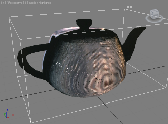
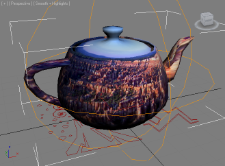
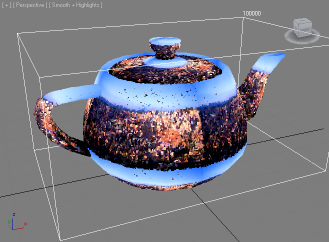
- In the following example, a default Teapot was assigned a Standard Material with a Bitmap Texture using the standard BRICE.JPG image shipping in the Maps/Background samples of 3ds Max.
- The Teapot was converted to particles using a PRT Volume object which also acquires the mapping coordinates found in the Mapping Channel 1 generated by the Teapot primitive into the TextureCoord channel of the particle cloud.
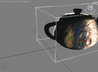
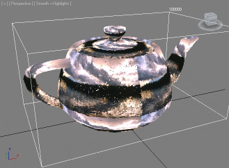
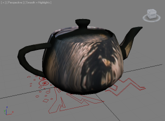
- In the next example, a UVW Mapping modifier in Spherical mode was applied to the Teapot and set to Map Channel 2.
- The Bitmap texture map was also switched to Map Channel 2 and the new spherical mapping was correctly propagated onto the PRT Volume’s particles:
Explicit Mapping and Particle Flow Particles
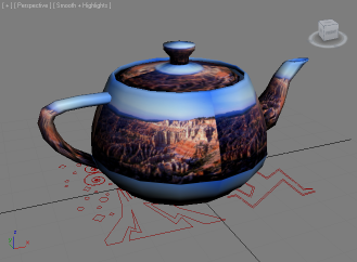
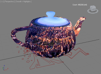
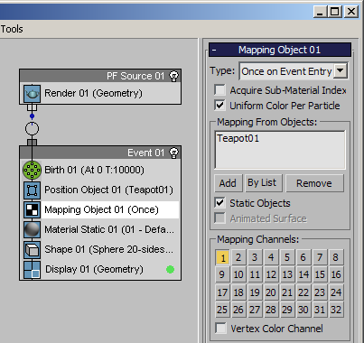
- In the following example, the same Teapot from the PRT Volume example above was picked as the Particle Object source to distribute particles on the surface.
- The Mapping Object operator available in 3ds Max 2010 and higher (previously available in Particle Flow Tools Box #1 and the 3ds Max 2009 Extension) was used to acquire the Teapot’s Mapping Channel 1.
- The Bitmap texture map was switched back to Map Channel 1 and its Material was assigned to the particles using a Material Static operator.
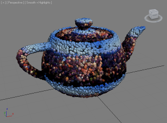
- The Shape of the particles was set to Sphere and the Display operator to Geometry to visualize the texture in the viewports - for Krakatoa rendering, the Shape operator can be omitted.
Explicit Mapping and PRT Loader Particles
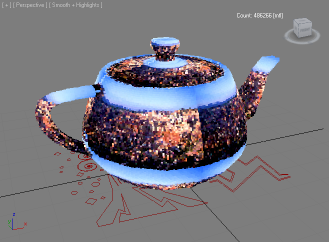
- Let’s take the above Particle Flow and save it to a PRT file.
- In the “Save Particles” rollout, we will specify the Position, Color, ID and TextureCoord channels for saving and save 100K particles to a PRT file.
- The Particle Flow contains both the Map Channel 1 data that goes to the TextureCoord particle channel and the evaluated Material’s color with the bitmap texture which goes into the Color channel, so we have both the texture baked and we could replace it with a new one if desired.
- Let’s create a PRT Loader and select the saved PRT file - the particles will display the baked Material/Texture map color (left image).
- If we would assign the Standard Material with the bitmap to the PRT Loader, it would appear IDENTICAL to the left image, but would render a bit slower since the material will have to be evaluated for each particle.
- But since we also have the TextureCoord channel stored in the PRT Loader, we have the flexibility to replace the Bitmap texture map at any time by picking a different file in the Standard Material!
Explicit Mapping Using Magma
- A Krakatoa Channels Modifier could be used to populate the Mapping Channels with data.
- For example, dumping the Position channel (which is in Object coordinates) into the TextureCoord channel would be equivalent to the “XYZ to UVW” mode of the UVW Mapping Modifier used on geometry.
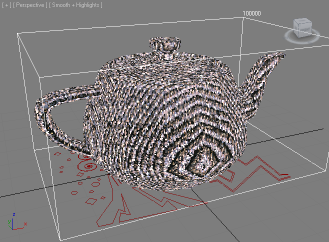
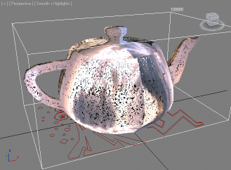
- The following images show the PRT Loader with KCM converting Position to TextureCoord on the left, the original Teapot with UVW Map set to “XYZ to UVW” on the right for comparison:
- Obviously, the position values change too fast, so we have to reduce the tiling by either dividing the Position values or by providing less-than-one tiling values to compenstate.
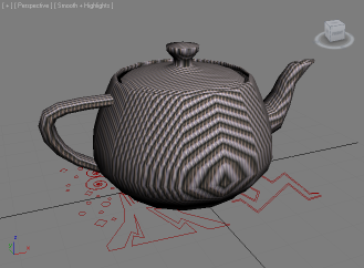
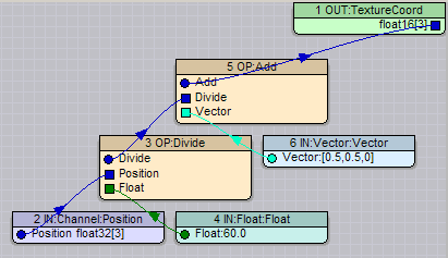
- In the following images, the Position value in the MagmaFlow was divided by 60.0, while the UVW Mapping Tiling values were set to 1/60.0 which is 0.016666 or 0.017 when rounded up:
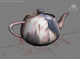
- Since the origin of the Position values is in the center of the teapot’s XY plane (at the object’s pivot), we might want to offset the UVs by 0.5 to align the center of the bitmap to the center of the teapot.
- In the examples below, the Position value after division was offset by 0.5 along U and V in the MagmaFlow (left image), while the right image shows an additional UVW Offset modifier with 0.5 in the U and V Offset fields to produce the same result:
Implicit Mapping
Planar From World XYZ
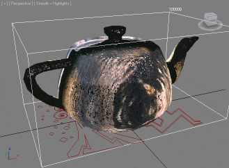
- When the Bitmap texture map is switched to “Planar From World XYZ”, the result looks very similar to the example of MagmaFlow with Position->TextureCoord, but with the difference that moving the object in world space will make it move through the texture.
- To compensate for the high tiling, the Tiling of the Bitmap texture map has to be adjusted to a value lower than 1.0.
- For example, with a value of U:0.01 and V:0.01, the PRT Loader looks like the image on the left.
- If the PRT Loader is moved, the texture remains fixed in world space and the particles move through the texture (right image):