Krakatoa MY Introduction To Magma
Applicable to Krakatoa MY 2.3.0 and higher
- Overview
- The Scene Setup
- Opening The Magma Editor
- My First Magma Flow - Color By Normal
- My Second Flow - Gradient By Normal Y Component
- Removing The Multiply Node
- Extracting The Y Component Of A Vector
- Converting The Y Component To A Vector
- Dealing With The Negative Values
- Creating a Grayscale Gradient
- Changing The Normal Input To Position
- Scaling Down The Position Input
- Blending Two Arbitrary Colors
- Swapping the Input Socket Connections
- Connecting The Divisor To The Sphere Radius
Overview
- In the following tutorial we will look at some simple examples of channel editing and will present some fundamental workflows of the Magma channel editor introduced in Krakatoa MY v2.3.
- In these first tutorials, you will learn about creating nodes and connections including auto-connecting and auto-reordering the flows, understanding error messages, removing nodes from the flow while preserving connections, toggling nodes on and off, extracting components from Vector channels, convering Floats to Vectors, blending colors using a control value, swapping input sockets, and more.
The Scene Setup
- For our first test with Magma, let’s create a very simple scene containing just a single PRT Volume object.
- In the Maya menus, go to Create>Polygon Primitives>Sphere and create a Sphere object anywhere in the scene. Set the Radius to about 5.0.
- With the Sphere still selected, click the VOL icon on the Krakatoa shelf to create a PRT Volume object and connect the Sphere as its input.
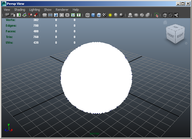
RESULT: A white sphere made of particles will appear in the viewport.
Opening The Magma Editor
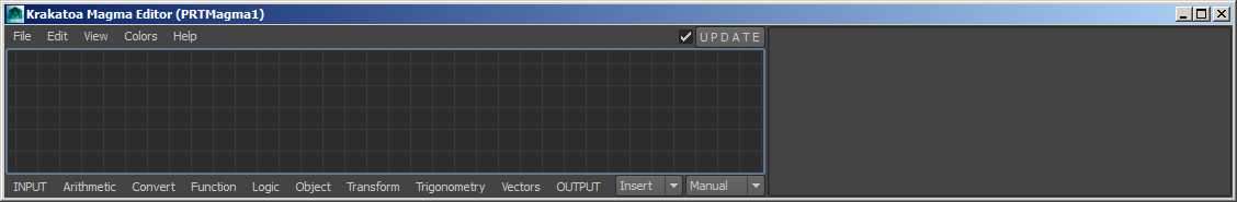
- With the PRT Volume object selected, click the MAGMA icon on the Krakatoa shelf to connect a new Magma node to the object and open its Magma Editor.
- You can resize the Magma Editor dialogs like any other windows in Maya, but there are limits to the minimal size based on the length of menus and other controls.
My First Magma Flow - Color By Normal
- To understand the basic functionality of the Magma editor, let’s create a very simple flow that takes the particle’s Normal channel and outputs it as the particle’s Color. Note that a PRT Volume object generates a Normal channel by taking the surface normal of the volume mesh from the closest point to the particle’s position.
- Creating An Output Node Using The “Node Depot” Menus
- Click the OUTPUT menu item at the bottom-center of the Editor’s UI - a menu will open up, containing some typical channels accessible in Krakatoa.
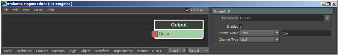
- Select the “Color C” entry to create an Output node set to the Color channel.
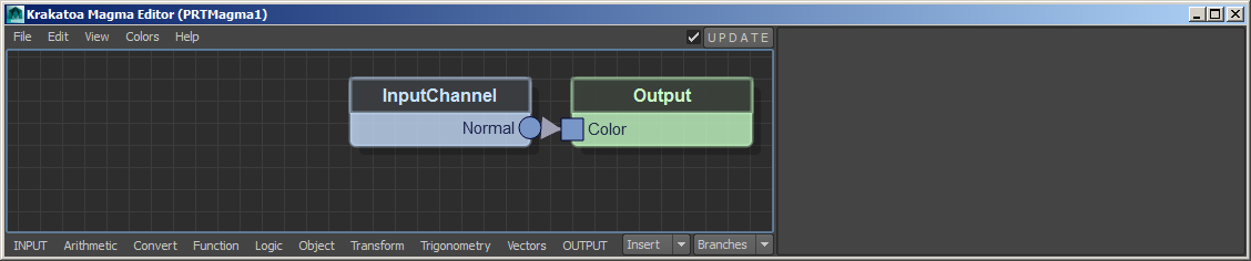
RESULT: A green node with title Output and input socket labeled “Color” will appear in the Editor. The socket will be drawn in red, showing that the node needs an input to be connected to it to operate correctly.
- The node’s outline will be white, showing that it is currently selected. The attributes of this new node will be listed in the Magma Editor’s own Attribute Editor panel on the right side. These attributes are:
- Description - the default name of the node is set to the Type of the node. You can enter any description here.
- Enabled - a checkbox that lets you toggle the channel output on and off.
- Channel Name - a drop-down list with some useful channel name presets and a text field for typing in custom names
- Channel Type - a drop-down list with supported channel types which will be set automatically when selecting a pre-defined Channel Name entry, or can be switched manually when entering a custom channel name.
Note that you could change the channel name to any other pre-defined name at any time in the future, or type in your own custom channel names in the text field to create a new arbitrarily named channel of any supported type.
Creating An Input Node Using The Depot’s Keyboard Shortcuts
- Make sure the Output node is still selected. If it is not (outline is black) because you clicked somewhere in the Editor, click the node again to select it.
- As an alternative to clicking the INPUT menu item at the left side of the botom menu bar, let’s access it using its keyboard shortcuts - press the ALT key on your keyboard and while holding it down, press “I” which is the keyboard shortcut of the INPUT menu. A menu containing several items and sub-menus will open up.
- Instead of clicking with the mouse, press the C key to activate the “InputChannel C” sub-menu item (the letter to the right of the menu item tells you the shortcut!), and then press N to activate the “Normal N” item from its sub-menu list of typical channels.
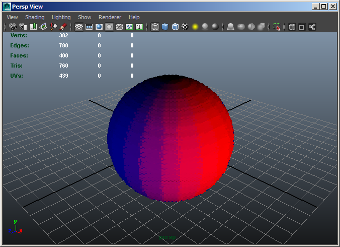
RESULT: A new blue node with title InputChannel node and output socket labeled “Normal” will appear in the Editor to the left of the previously selected node. It will be auto-connected to the input socket of the Output node because Magma will attempt to auto-connect to the last selected node whenever a new node is created. This can save a lot of time and makes building flows quickly much easier. Both sockets will be drawn in blue which shows that the data will flow between them.
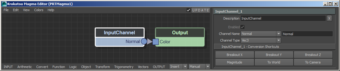
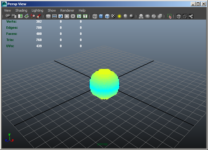
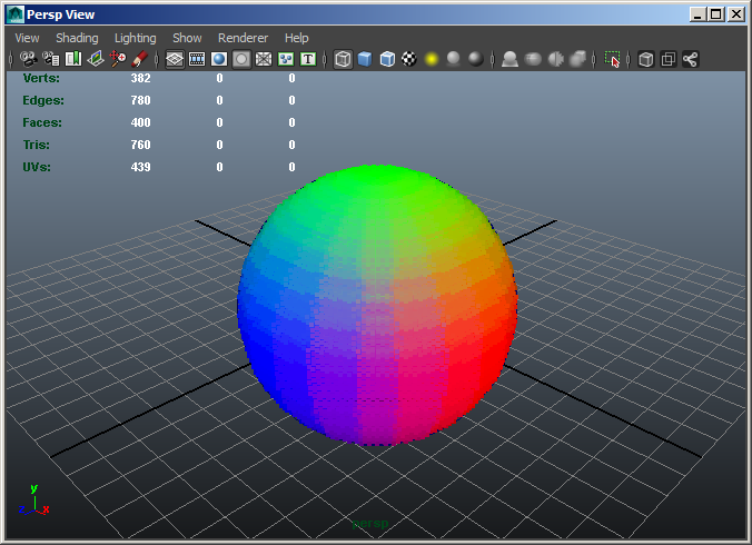
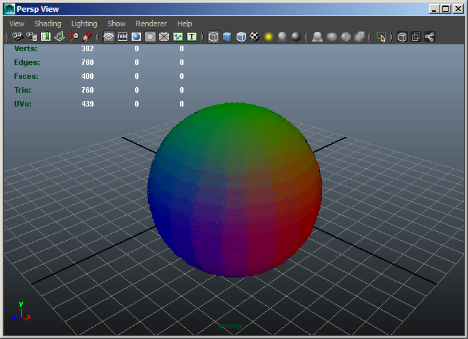
At this point, the PRT Volume particles in the scene will appear in all colors of the rainbow thanks to the Normal vectors being copied into the Color channel.
Inserting A Multiply Operator Node Using Direct Keyboard Shortcuts
- Let’s multiply the incoming Normal value by a Floating point number to make the colors darker or brighter.
- We already saw two possible workflows for creating Magma nodes - clicking with the mouse in the “Node Depot” menus at the bottom of the Editor, or accessing the same menus using its keyboard shortcuts. We could easily create a Multiply node by clicking the Arithmetic > Multiply menu items with the mouse, or by pressing ALT+A for Arithmetic, and then M for Multiply.
- But the Magma Editor provides another set of direct keyboard shortcut accelerators which can be used to create the majority of often-used nodes much faster, often with a single key press! For example, the shortcut for creating a Multiply operator is the actual * multiply key on the Numeric Keypad!
- Make sure the InputChannel node is still selected, if it is not, select it by clicking it with the mouse.
- Press the * key on the Numeric Keypad of your keyboard.
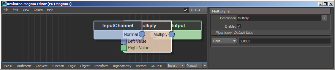
RESULT: A new Multiply node will be inserted into othe existing connection between the InputChannel Normal and Output Color nodes. The insertion will be performed by connecting the first (and only) output socket of the InputChannel node into the first input socket of the Multiply node, and the first output socket of the Multiply node to the first (and only) input socket of the Output node. The connected sockets will be drawn in blue. The unconnected second socket of the Multiply node will be drawn in green, showing that while it has no incoming connection, it is still valid because it has its own default value (listed in the Magma Attribute Editor panel).
- As a rule of thumb, a new Operator will always be inserted AFTER the currently selected node, unless the selection is an Output node (in which cache it will go BEFORE the Output). If there is an existing connection between the top sockets of the selected node and whatever node it is connected to, the new operator will be inserted into it. If there is no existing connection, a new connection will be made from the selected node to the newly create one.
- When the new node is an Input, it will be naturally connected to the first empty input socket of the existing selection. If the new node is an Output, its input socket will be connected to the first output socket of a pre-selected Input or Operator node.
Auto-Reordering The Flow
- You will notice that the new Multiply node was placed half-way between the two existing ones. But since they were too close to start with, the new node is overlapping both. To solve this, we can toggle the Auto-Reoder feature of the Magma Editor.
- Press Ctrl+R, or alternatively switch the “Manual” item in the drop-down list in the bottom right of the Editor’s UI to any other mode, for example “Branches”. (With only three nodes, you won’t see a difference in the resulting order from the non-manual modes.)
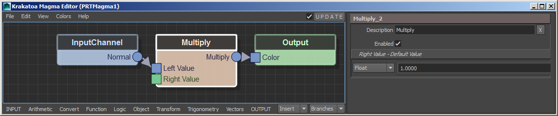
RESULT: The nodes will be reordered, leaving enough space for the Multiply node to appear between the InputChannel and the Output nodes.
Changing The Multiply Value
- Some nodes like most Arithmetic operators provide default values for their unconnected sockets. In the case of the Multiply node, even though we have not connected anything into the second, “Right Value” socket, we can still enter any Float value we like in the Attribute Editor palen of the Magma Editor!
- Select the Multiply node if it is not selected
- In the Attribute Editor panel, change the Right Value > Float value to 0.5
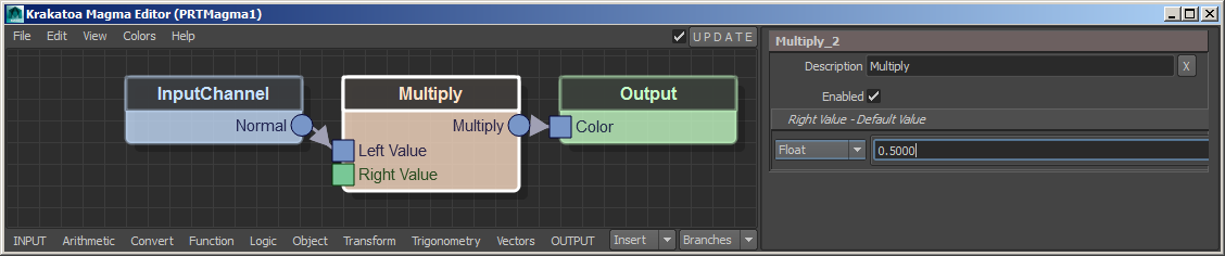
RESULT: The Colors in the viewport will become half as intense.
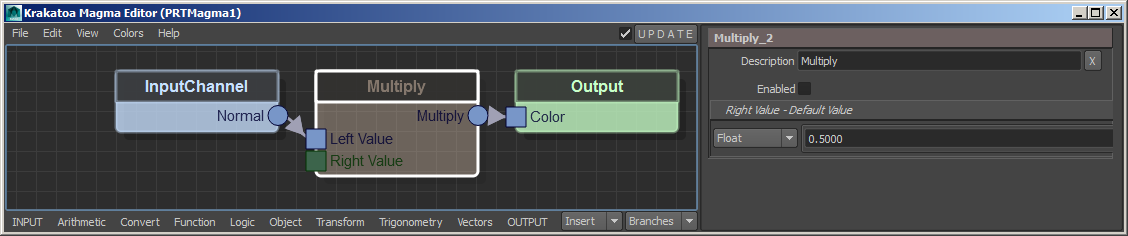
Toggling A Node On and Off
- Some nodes in Magma provide a so-called “Pass-Through” mode - the value coming into their first input socket will be passed unchanged into the first output socket. This feature is controlled by the “enabled” attribute we saw earlier.
- Select the Multiply node if it is not selected.
- In the Magma Attribute Editor panel, uncheck the “Enabled” property.
RESULT: The node will be drawn as transparent to denote it was disabled, and the InputChannel Normal value will pass through unmultiplied directly to the Output Color channel. The particles in the viewport will turn back to their original brighter rainbow colors.
- We can easily re-enable the Multiply node by checking the “Enabled” property again, but we can do this even faster by using the keyboard shortcut CTRL+P (short for Pass-Through).
- Make sure the Multiply node is still selected.
- Press CTRL+P to toggle the Pass-Through mode of the selected node.
RESULT: The multiplication will be performed again and the viewport particles will become darker. You can press the keys repeatedly to toggle on and off several times. Note that the CTRL+P shortcut can be applied to ANY number of selected nodes, not just a single one. This is why it is a much faster approach than clicking the “enabled’ property.
Multiplying By Vector
- In the previous steps, we were multiplying all three components of the Color (R,G and B) by the same Float value. Let’s multiply by a Vector value, so we can suppress some channels and boost others independently.
- Make sure the Multiply node is selected.
- Change the drop-down list in the “Right Value” panel from “Float” to “Vec3”.
- Enter 1.0 in the first field, 0.0 in the second field and 0.5 in the third field.
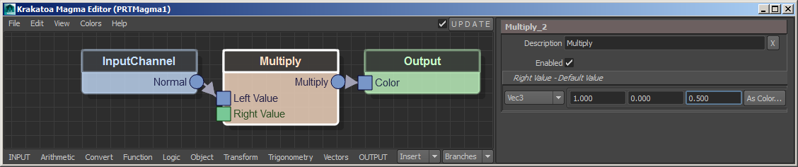
RESULT: The Red component will be left untouched, the Green component will be suppressed completely, and the Blue component will be halved.
At this point, you might want to save the Maya scene to disk.
My Second Flow - Gradient By Normal Y Component
- For the next example, we will reuse the same scene and even the same basic Magma flow, but this time we will extract the Y component of the Normal Vector and will produce a gradient from it.
Removing The Multiply Node
- As a first step, we want to remove the Multiply operator we used previously, but without disturbing the existing connection passing through it. So instead of pressing the DEL key which would delete the node and all its connections, we will press the BACKSPACE key which removes the node while preserving the existing connection.
- Select the Multiply node if it is not selected yet.
- Press the BACKSPACE key on your keyboard
RESULT: The Multiply node will be removed from the flow and will be deleted permanently, but the connection between the InputChannel and the Output nodes will remain intact!
Extracting The Y Component Of A Vector
- Now we want to extract only the second component (vertical axis value) of the Normal channel. The node to do this is called Breakout and could be accessed from the Convert category in the Nodes Depot menu, but an InputChannel node loading a Vector channel already provides a more convenient shortcut to that node.
- Select the InputChannel node in the Editor.
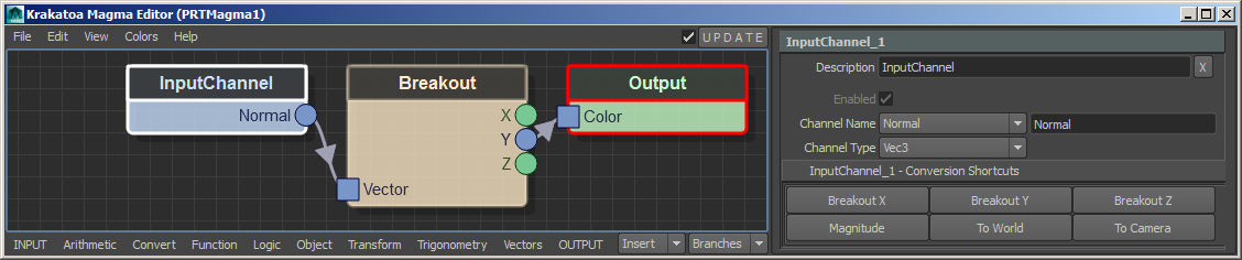
- In the Attribute Editor panel of the Magma Editor, click the “Breakout Y” button found in the “InputChannel_1 - Conversion Shortcuts” panel.
RESULT: A new Breakout node will be inserted between the InputChannel and Output nodes, and its second output socket (Y component) will be connected to the Output Color socket.
- Note that the Output node has a red border now, and the Maya Script Editor will display an error because the output of the Breakout is a Float, but the Color channel is expected to be a Vector.
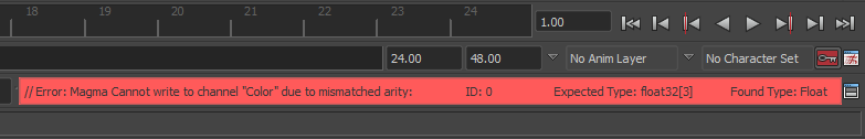
- The error says that the channel “Color” has a mismatching arity. “Arity” is the number of components of a value. In other words, a Float has an Arity of 1, a Vector has an Arity of 3, and a Quaternion has an Arity of 4.
Converting The Y Component To A Vector
- So now we have to turn the Float of the Y Normal component to a Vector again before it can go out as Color channel. There are several ways to do this, so let’s first just use a Convert > ToVector operator.
- We want to insert the new ToVector operator between the Breakout and the Output nodes. But we cannot select the Breakout and insert behind it because the existing connection is coming out of the second output socket of the Breakout, and the insertion only works with the top (first socket) connections. Thankfully, the Output node has only one input socket, so in this case, we could select the Output node instead, then create the ToVector and it will be inserted correctly.
- The alternative and much safer approach would be to select the connection itself, then create the new node to be inserted!
- Click on the existing connection (arrow) between the Breakout and Output nodes to select it.
- Press ALT+C for Convert and V for ToVector, or use the mouse to click the respective menu items.
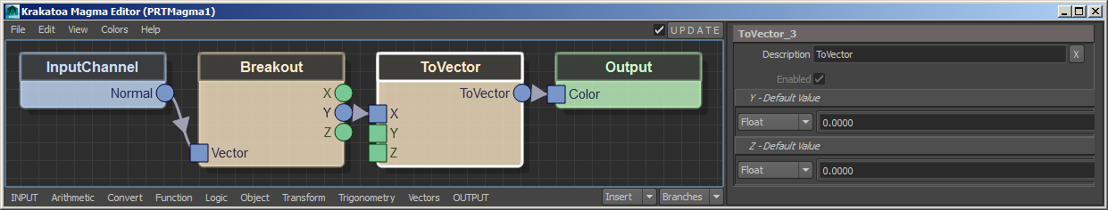
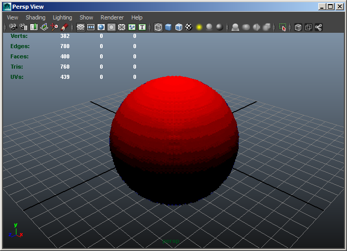
RESULT: The new ToVector node will be inserted within the selected connection using its first input socket and first (and only) output socket. Because we are setting only the first component of the ToVector to the Y component of the Normal, and the Y and Z default to 0.0, the result is a red gradient from the equator to the north pole of the particle sphere. Negative values below the equator produce black color.
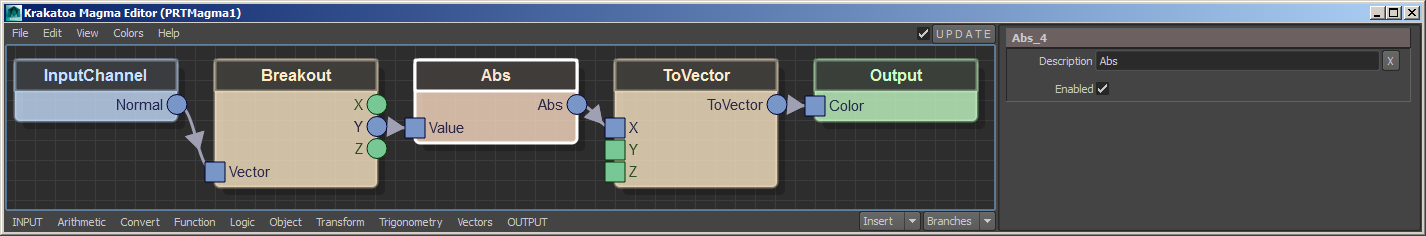
Dealing With The Negative Values
- To get rid of the negative values below the equator, we can simply use an absolute value operator, found under Arithmetic > Abs.
- Click on the connection between the Breakout Y output socket and the ToVector X input socket to select it.
- Press ALT+A for Arithmetic, then B for Absolute.
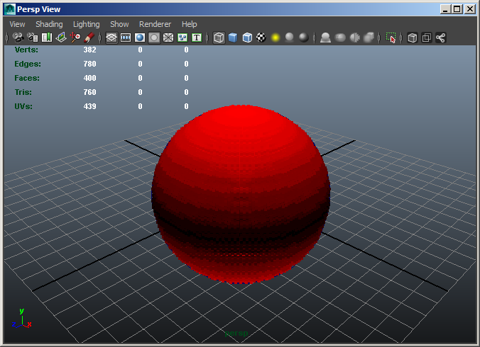
RESULT: A new Abs node will be inserted in the selected connection, removing the negative sign from the Y Normal component.
The color in the south pole areas of the spherical particle cloud will now be bright just like in the north pole areas:
Creating a Grayscale Gradient
- Obviously, we could change the Red Gradient to a Grayscale Gradient by simply connecting the output of the Abs node to the second and third input sockets of the ToVector node.
- Drag a new connection with the mouse from the output socket of the Abs node to the Y input socket of the ToVector node.
- Repeat the same, but this time connect from the output socket of the Abs node to the Z input socket of the ToVector node.

RESULT: The same value now goes into all three components of the Color, and the particles turn gray in the viewport accordingly:
Changing The Normal Input To Position
- We can achieve a similar result by using the Y component of the Position channel instead of the Normal.
- Select the existing InputChannel node.
- In the Attribute Editor panel of the Magma Editor, change the Channel Name from “Normal” to “Position”.

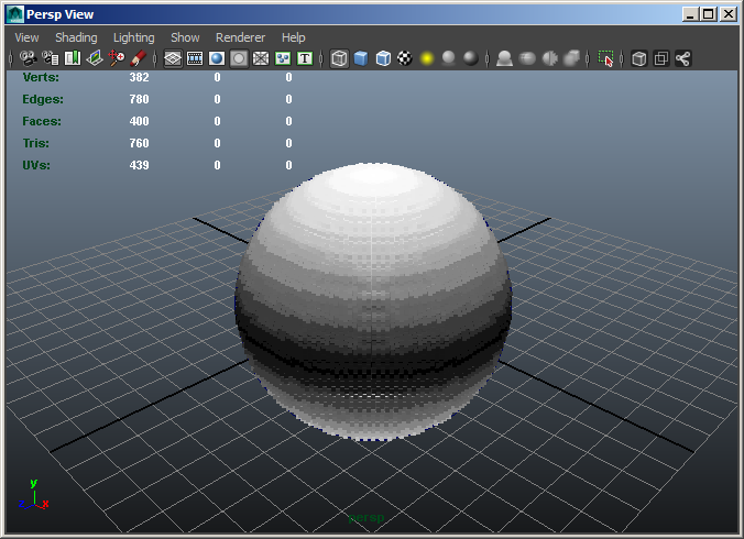
RESULT: The particles will turn mostly white because the Sphere Radius was 5.0, but the Position Y produces a visible gradient only between 0.0 and 1.0.
Scaling Down The Position Input
- To make the gradient smoother, we can divide the Position (either the whole Vector or just the Y component) by a Floating point number representing the Sphere’s Radius.
- Select the InputChannel node.
- Press the / key on the Numeric Keypad to insert an Arithmetic > Divide operator.
- Enter 5.0 for the Divisor value in the Magma Attribute Editor.
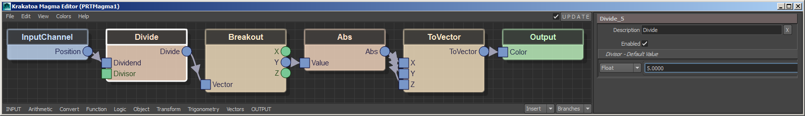
RESULT: The gradient will now run again from white at the north and south poles to black at the equator.

Blending Two Arbitrary Colors
- Instead of turning the Float component of the Position or Normal InputChannel to a Vector value directly, we can use it to control the Blending of any two custom Color values.
- Click the ToVector node to select it.
- Press BACKSPACE to remove it while preserving the existing connection.
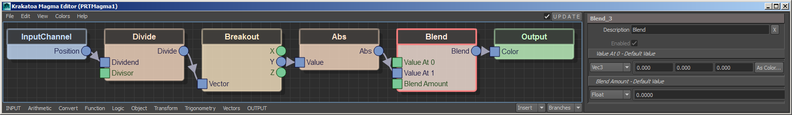
- Select the Abs node or the connection coming out of its output socket, and press ALT+F for Function category, and then B for Blend.
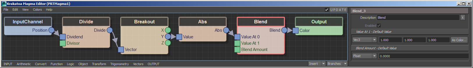
RESULT: The new Blend node will be inserted into the flow. It will be highlighted in pink (both selected, and with an error), because the connection is currently wrong -a Float value is once again coming from the Abs node, but the second input socket of the Blend is already set to Vec3 to match the requirements of the Output Color node. Thus the error complains that the two first sockets cannot be mixed because they are of incompatible types.
Swapping the Input Socket Connections
We could fix the above error manually by connecting the output of the Abs node to the third, control input of the Blend node which provides the Blend Amount as a value between 0.0 and 1.0, and by deleting the existing connection from the Abs output to the first socket of the Blend node.
But there is once again a more convenient way to swap existing connections coming into the first three input sockets. The two shortcuts to remember are CTRL+W which swaps the first and the second input connections, and SHIFT+CTRL+W which does the same with the second and third input connections.
- With the Blend node selected, press CTRL+W - this will swap the first and second connections and the existing connection will end up at the second socket.
- Press SHIFT+CTRL+W - this will swap the second and third connections, moving the existing connection to the third socket, where it belongs.
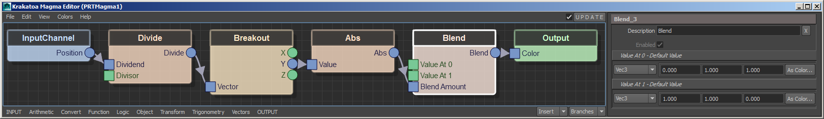
- Click the “As Color…” button in the “Value At 0” panel in the Magma Attribute Editor to select the color to use where the control value is 0.0. For example, pick the Cyan preset.
- Click the “As Color…” button in the “Value At 1” panel abd select another color, for example the Yellow preset.
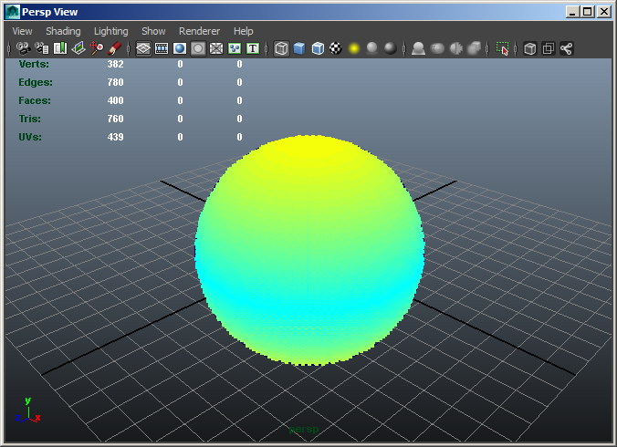
RESULT: The error is now gone because the Float output of the Abs node goes into the correct, Blend Amount socket of the Blend node. The two colors we specified will be mixed according to the scaled down Y component of the particle’s Position.
Connecting The Divisor To The Sphere Radius
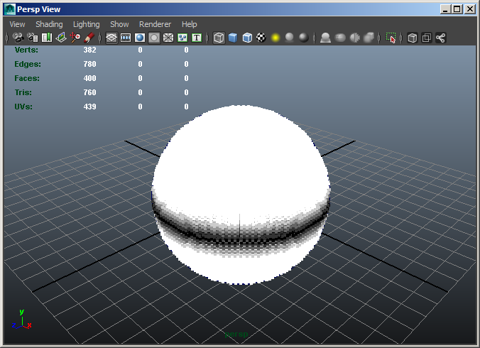
- Currently, we are dividing the Position value by a static value of 5.0 to match the Radius of the Sphere that defines the size of the PRT Volume’s particle cloud. But if we would animate the Sphere Radius, the static value in the Magma would produce the wrong gradient. For example, if we would keyframe the Radius at frame 1 to 5.0 and at frame 24 to 2.0, the gradient on frame 24 would look like this:
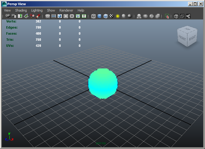
To adapt the size of the gradient to the new size of the Sphere on each frame, we would also have to animate the Divisor.
Obviously, using a Maya Expression to connect the value of the Divisor to the value of the Sphere Radius would be the best solution.
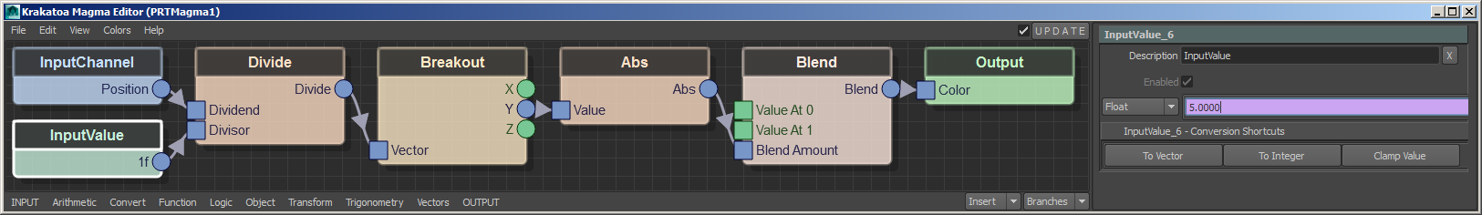
While it is possible to assign the Expression to the default value of the Divide operator’s second socket, it is recommended to connect a dedicated InputValue to the Divisor socket to control the value. This provides more flexibility since we could insert other nodes between the value and the Divide operator, for example a Clamp node to keep the incoming value in a specific range.
- Select the Divide operator
- Press CTRL+2 to create a new Float InputValue with a value of 2.0 - on frame 24, the gradient will now look ok, but it would be wrong on frame 1.
- In the Magma Attribute Editor, right-click the value field and select “Create New Expression”
- In the Expression field, enter the following expression:
PRTMagma1.InputValue_6_Property2_fValue_Float = polySphere1.radius
- In the Expression Name field, enter a name like “DivideBySphereRadius”
- Click the Create button on the Expression Editor to create the expression.
- Click the Close button on the Expression Editor to end the editing session.
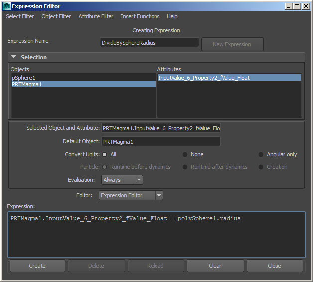
RESULT: The value field will turn purple and the InputValue will now pass to the Divisor the same as the Radius of the Sphere.
- Moving the time slider between 1 and 24 will keep the color gradient sized exactly to the Radius of the Sphere.