Stoke Particle Simulator User Interface
The Stoke Particle Simulator exposes the following controls in the Modify tab of the 3ds Max Command Panel.
Help rollout
The Help rollout contains the About information and version, as well as the following controls:
Open Online Help… button
- Pressing this button will open the Online documentation.
- Internet connection and a Web Browser are required to use this documentation.
Log Level drop-down list
- Controls the type of information shown in the MAXScript Listener during simulation:
- None - nothing will be reported.
- Error - only errors will be reported.
- Warning - both warnings and errors will be reported.
- Progress - progress messages, warnings and errors will be reported.
- Stats - all reportes except for debug messages will be shown.
- Debug - full reporting including debug information will be performed.
Saving and Caching rollout
Save Path controls
- The edit text field shows the base save path where the Stoke MX will save PRT files.
- By default, the path will be set in the user’s local data folders via a $default symbolic path. It resolves to C:Users[YOURUSERNAME]AppDataLocalThinkboxStokeCache
- You can specify any absolute path you want as the Base path instead.
- Each Stoke object will generate a unique random ID upon creation. This ID will be used to create a sub-folder called Stoke_XXXX_YYYY within the Base folder.
Folder button
- Left or Right-clicking the button on the right side of the Save Path will open a menu with the options to
- Open a directory browser to pick a different base path;
- Save the currently specified path as default for future Stoke objects;
- Reset the base path to the last stored default value;
- Open the Windows Explorer at the output path.
Version field
- This field defines the sub-folder within the <BasePath>Stoke_XXXX_YYYYpath in which to store the Stoke disk cache.
- If no folders exist in the base folder yet, the default name will be “v001”.
- If folders exist in the base folder, each new Stoke object will create a version folder with one higher than the last number found in the sub-folders names. For example, if there are folders called “v001”, “tk102” and “bobo234”, the next folder created will be “v235” because “234” is the largest number found in any of the sub-folders.
- You can enter ANY valid folder name instead of a version string, for example “test”, “temp” and “deleteme” are all valid names even though they contain no numbers.
- You can enter an existing sub-folder name - this will set your Stoke object to use that folder and will potentially connect the Memory Cache to the existing Disk Cache.
Version Presets button
- Clicking the [>>] button next to the Version field will open a menu with the options to
- Create a New Folder - a new version folder with the next available number will be created.
- Set an existing folder as the current Disk Cache
File Name Prefix field
- The second field next to the version folder defines the file prefix to save to.
- The default name is “Stoke”, and it will produce PRT files named “Stoke_0000.prt” etc.
- You can enter any name prefix to produce a new sequence within the current version folder.
Disk Space Info field
- This field displays information about the available disk space in GB on the disk drive specified for cache output, as well as its file system format and its type.
- If the output is set to a network locatiom, the display might show “Disk Space Data Not Available”.
Cache Options group of controls
Save Indicator
- The color swatch to the left of the >Save Disk Cache button indicates whether there are PRT files pending to be written by the background thread.
- When it is red, PRT files are still being written from the pending memory buffer to disk.
- When it is green, all files have been written to disk.
- When it is gray, no simulation data has been found in the Stoke object.
>Save Disk Cache checkbutton
- When checked, the Disk Cache will be used and PRT files will be saved by an asynchronous background thread during and after the simulation.
- When unchecked, no saving will be performed and all simulation data will be cached in the Memory Cache only.
[+] button
- Pressing this button will create a new PRT Loader, set to load the Disk Cache saved by the current STOKE MX object.
- If any frames are still pending, they will be saved first (in other words, a Cache Flush will be performed first which can take a while depending on the size of the simulation).
Cache Nth value spinner
- Default is 1.
- When set to 1, every frame in the specified Memory Cache range (or Simulation range) will be stored in memory.
- When set to a value above 1, only every Nth frame will be cached in memory, and all intermediate frames will be interpolated from their neighbors - see Retiming and Use Playback Interpolation for more details.
Memory Limit spinner
- This value defines the Memory Cache limit in Megabytes.
- The Memory Cache Limit is used to cap the memory usage of the Stoke object.
- The Limit will be shared by the Memory Cache and the Pending Saving Buffer automatically.
- During simulation, the majority of the Limit will be allocated to the Pending Buffer. Once the data is cached to disk, the memory will be passed back to the Memory Cache for faster playback.
Used Memory field
- This text field shows the memory usage of the Memory Cache and the Pending Buffer.
[X] button
- Pressing this button will open a context menu with the following options:
- RESET the Memory Cache. This option will clear the Memory Cache and all unsaved simulation data will be lost. It will not affect the Disk Cache, so if PRTs were written to disk, they will be preserved. If the background was still saving PRTs, the current file will be saved and the rest will be skipped.
- FLUSH the Memory Cache - Save to Current Cache Path. This option will force any unsaved simulation data to be written to disk. This will happen in the Main Thread and NOT in the background, so it might lock the computer for a long time.
- Save the Cache to a NEW PRT Sequence. This will force the resaving of all existing data to a new file sequence at a user-defined path. This will happen in the Main Thread and NOT in the background, so it might lock the computer for a long time.
Cache Usage Graph
- The graph shows the content of the Stoke Memory and Disk Caches using one pixel wide bars to represent each frame of the simulation.
- The graph is 150 pixels, thus showing 150 frames in a row.
- If more than 150 frames were simulated, multiple rows will be used.
- Each 10th frame will be drawn slightly darker to produce a reference grid.
- The current frame will be drawn slightly lighter.
- Gray color means “unused”
- Red color means “data missing”. This is the case for example if a simulation was canceled prematurely (see the screenshot), or if simulating with Every Nth frame (in-between frames will be shown in red).
- Blue color means “exists on disk, but not in memory”. These are frames that have been written to disk, but have been unloaded from the Memory Cache. They can be loaded if the respective frame is requested by the scene time.
- Green color means “loaded in memory”. These are frames that have either been saved to disk and are also in memory, or are in memory and still not saved to disk.
- If the Memory Limit is set relatively low or the particle count is very high, dragging the time slider will cause the graph to display portions of green and blue changing to show dropping of frames from memory (green becoming blue), and disk data being loaded into memory on demand (blue becoming green).
Simulation Rollout
Simulation Options group of controls
SIMULATE button
- Pressing this button will perform the particle simulation according to all other settings described here.
- A STOP button and a progress bar will appear in 3ds Max 2011 and higher - pressing the button will stop the simulation prematurely. In 3ds Max 2010, a 3ds Max UI progress bar with Cancel button will be displayed instead. Pressing the Cancel button will stop the simulation.
RESUME button
- Pressing the RESUME button will continue the simulation.
- It is initually grayed out.
- It will become available if the simulation has been stopped prematurely, or if the Simulate Until spinner is set to a higher value than the last simulated frame.
- It will be disabled if any relevant simulation settings including the distribution and velocity field objects are changed. Changing the values back to their last settings during the simulation will reenable the button.
- The animatable parameters (Rate/Frame and Velocity Scale) and the Cache options (Memory Limit, Cache Nth) can be changed before resuming.
Simulate From value spinner
- This value defines the start of the simulation range.
Cache From checkbox and value spinner
- The checkbox is unchecked by default.
- When checked, the simulation will start on the frame defined by Simulate From value, but no caching will be performed before the Cache From frame.
- This allows for Pre-rolling the simulation and saving only the frames that matter.
Simulate Until value spinner
- This value defines the end of the simulation range, and implicitly also the end of the caching / saving interval.
Sub-Steps value spinner
- This value defines the number of sub-steps within a single frame.
- The default value is 1, producing one step per frame.
- Increasing the value will perform multiple sub-steps within the frame interval, potentially capturing finer details
- This is especially useful when using fast-moving particles as Velocity Field that can jump over voxels within a frame.
- Note that increasing the Sub-Step value will increase the simulation time proportionally.
Preview Nth checkbox and value spinner
- When the checkbox is checked, the viewport will be updated during simulation.
- The value spinner defines the Nth frame to update if the checkbox is checked.
- Default is 5, update on every 5th frame.
- Setting the value to 1 will update each frame during simulation, resulting is some overhead.
Particle Birth group of controls
Emit Start and Emit End value spinners
- These two values define the beginning and end of the particle emission.
- They can be set to a sub-set of the Simulation range to produce particles only within a small interval or even on a single frame, but simulate a longer animation after that.
- This can be used as a quick way to set a single short burst of particles. For any more complex behaviors like multiple pulses, gradual increase and decrease of particle rates etc, consider animating the Rate/Frame value described further on this page.
Rate Type drop-down list
- This control provides several methods for controlling the particle generation rate:
- Total Rate, Relative Split - in this mode, the total rate will be split between all distribution objects according to their per-source rate values.
- Total Rate, Equally Split - in this mode, the total rate will be divided equally between all distribution objects.
- Total Rate, Every Source - in this mode, every distribution object will emit the number of particles specified by the Rate/Frame value.
- Absolute Per-Source Rate - in thus mode, the Rate/Frame value will be ignored and the per-source rate values will be used instead.
- Note that if a distribution object is set to match the particle count of another particle system, the user-defined object rate will still be used for the calculation of percentages, but the actual source object particle count will be used for the emission.
Rate/Frame value spinner
- This value specifies the number of particles to generate per frame if the Rate Type option is set to a “Total Rate…” mode.
- This value can be animated over time.
Total Count text field
- This text field shows an estimate of the total number of particles that will be created based on the current settings.
- This value will not take into account emission from PRT sources with variable particle count and the option to match the Seed Count enabled.
Particle Lifespan rollout
Delete ‘Dead’ Particles checkbox
- When checked, particles whose Age is greater than the LifeSpan value will be removed from the simulation.
- When uncehcked, the Age and LifeSpan channels will still be generated, but particles with Age greater than LifeSpan will remain in the simulation and can be deleted afterwards using a Krakatoa Magma modifier.
- In the latter case, the Magma can modify the Age, the LifeSpan, or both to extend or shorten the simulated values and change how long the particles will live.
Up-Arrow button
- This button will be enabled only if Krakatoa is installed on the system.
- Pressing this button will create a set of a Krakatoa Magma modifier and a Krakatoa Delete modifier.
- The Magma modifier will select the particles with Age > LifeSpan and pass them up to be deleted.
Lifespan value spinner
- This value specifies the base life expectancy of the particles in frames.
- It is used to initialize the LifeSpan channel of each particle at its birth to a value (combined with the Variation value below) that defines how long the particle is supposed to exist.
- The LifeSpan channel is used together with the Age channel to either remove particles during the simulation (if Age is higher than LifeSpan), or to remove particles after simulation using Krakatoa Magma + Delete modifiers (if Krakatoa is installed). See above for details.
- The actual LifeSpan channel value is stored as Floating Point Seconds according to the current Frame Rate.
Variation value spinner
- This value defines a random variation in the LifeSpan in frames.
- The random value is generated at birth according to the Random Seed specified in the Distribution rollout.
- The random value is used to define a +/- range, in other words a Lifespan of 30 with Variation of 5 will produce random values between 25 and 35, consistent with the way Particle Flow defines variations.
Distribution rollout
Pick… button
- The Pick… button allows the picking of a scene object in the viewport to be added to the Distribution list.
- The Pick… button applies a filter to allow only valid mesh or particle sources to be added.
- Pressing the H key after clicking the button will open the Select By Name dialog.
- Only one object can be added at a time.
- To cancel picking, right-click in the viewport.
By Name… button
- The By Name… button allows the picking of multiple objects via the Select By Name dialog.
- The same filter will be applied to the dialog list as with the Pick… button.
Remove button
- The Remove button removes the currently highlighted object from the Distribution objects list.
- Only one object can be removed per click.
- The removal is currently not undoable!
Distribution Sources listView
- This list displays the distribution sources added to the Stoke object.
- The list provides checkboxes to activate or deactivate objects without removing them permanently from the list.
- The first column displays the name of the object, with the color reflecting the type of the emitter (particles or mesh) or the mesh emission mode (surface, volume vertices, edges) in the latter case.
- The tooltip provides extended info at a glance including the name and type and all relevant emission parameters.
- The following columns also display the relevant parameters like Rate/Ration, Emit From, Sub-Set, Jitter and Spacing.
- The Rate column will display
- the absolute Rate specified for the object if the Rate Type is set to “Absolute Per-Source Rate”,
- the Ratio % when set to “Total Rate, Relative Split”
- the calculated rate if set to “Total Rate, Equally Split” or “Total Rate, Every Source”
- “Auto” if “Use Seed Count As Rate” is checked for a Particle source.
- Right-clicking an object on the list will show a menu with two options
- Hide Object - toggles the hidden state of the object. A checkmark will be shown in front of it when the object is hidden.
- Select Object… - selects the object in the scene. This will obviously switch the Modify Panel to the source object.
Jitter Radius value spinner
- This control is displayed only if any source is selected in the Distribution Sources listView.
- It defines the radius of the spherical region around the seed position in which to jitter the new particle’s initial position.
- It is only used at birth when the particle has an Age of 0.
Source Rate value spinner
- This control is displayed only if a source is selected in the Distribution Sources listView.
- It will be grayed out if the option “Use Seed Count As Rate” is checked for a Particle source.
- It defines the number of particles to generate from the selected distribution object if the Rate Type is set to “Absolute Per-Source Rate”, or the Ratio if “Total Rate, Relative Split” is selected.
Use Seed Count As Rate checkbox
- Displayed only if a Particle object is selected in the Distribution Sources listView.
- When checked, and only if the particles contain a valid ID channel, the Rate will match the source object regardless of all other Rate-related settings.
- When unchecked, or if no ID channel is found in the particles, the other Rate settings will apply.
Volume Spacing value spinner
- Displayed only if a Mesh object is selected in the Distribution Sources listView.
- Used only if the emission mode is set to Volume.
- This value cannot be animated over time.
Channels listView
- This listview shows all channels exposed by the active distribution sources (particles and meshes) specified on the Distribution Sources list.
- In Stoke 2.0 and higher, the list will also list several internal channels that are exposed by Stoke itself - Velocity, ID, Age, LifeSpan, and NormalizedAge. The latter is a single channel containing the Age divided by the LifeSpan as a gradient between 0.0 and 1.0.
- The list shows the name of the channel, and its type/arity.
- The color of the channel also represents the type/arity of the Channel:
- All Int channels are blue,
- float16 channels are dark green,
- float32 channels are light green,
- float16[3] (vector) channels are dark red,
- float32[3] (vector) channels are red
- By default, all channels except of Velocity, ID, Age and LifeSpan are unchecked.
- Check a channel’s checkbox to acquire the data from the distribution object.
- In Stoke 2.0 and higher, checking the checkbox also enables the saving of the channel to disk. Thus unchecking the Velocity, ID, Age or LifeSpan will disable the saving to the PRT sequence.
- If the distribution object does not provide a given channel, default values will be assumed for its particles.
- In Stoke 2.0 and higher, the type of the saved channels can be changed between 16 and 32 bit. All float and vector channels except for the internal Position channel (always 32 bit) now default to 16 bit to conserve disk space. In Stoke 1.x, they defaulted to 32 bit and could not be turned off.
- Select one or more channels on the list, right-click and use the context menu to switch the channel type between 16 and 32 bit.
- Note that Int channels have a fixed type of 32 bit except for the ID channel which is always 64 bit, and cannot be modified.
- The right-click context menu also provides quick options for select channels by type, e.g. all float16 channels, all float32[3] etc., as well as selecting all channels or inverting the current selection. This can be useful when you want to swtich all float16 channels to 32 for example.
Allow Multiple Object Picks checkbox
- When unchecked (default), a scene object that is a valid Distribution source can be picked by Stoke only once. After it is added to the Distribution sources list, it will not show up in the By Name dialog and will not be pickable by the Pick… button.
- When checked, the same scene object can be added more than once as Distribution source. This allows you to emit particles from both vertices and edges of the same mesh for example.
Emit From Viewport Particles checkbox
- When unchecked (default), Stoke will use the render state of the Distribution objects to emit particles from.
- When checked, the Distribution objects will not be switched to render mode and in the case of PRT objects, PFlow etc., the viewport particles will be used as seeds.
Random Seed value spinner
- This value is used to initialize the random distribution of particles at birth.
- Given the exactly same conditions (same objects, same particle counts and Stoke settings), this value ensures the same random patterns.
- Changing this value without changing any other parameters will change the resulting random pattern.
Velocity Field rollout
Pick… button
- The Pick… button allows the picking of a scene object in the viewport to be added to the Velocity Sources list.
- The Pick… button applies a filter to allow only valid sources to be added - supported Force SpaceWarps, particle systems, FumeFX grids, SIM Ember grids.
- Pressing the H key after clicking the button will open the Select By Name dialog.
- Only one object can be added at a time.
- To cancel picking, right-click in the viewport.
By Name… button
- The By Name… button allows the picking of multiple objects via the Select By Name dialog.
- The same filter will be applied to the dialog list as with the Pick… button.
Remove button
- The Remove button removes the currently highlighted object from the Velocity Sources list.
- Only one object can be removed per click.
- The removal is currently not undoable!
Velocity Sources listView
- This list displays the Velocity Sources added to the Stoke object.
- The list provides checkboxes to activate or deactivate objects without removing them permanently from the list.
- The first column displays the name of the object.
- The tooltip provides extended info at a glance including the name and type, the Velocity Scale, and some of the object’s properties.
- The second column displays the Scale.
- Right-clicking an object on the list will show a menu with two options
- Hide Object - toggles the hidden state of the object. A checkmark will be shown in front of it when the object is hidden.
- Select Object… - selects the object in the scene. This will obviously switch the Modify Panel to the source object.
Velocity Scale value spinner
- This value can be used to set the Velocity Scale of the currently selected Velocity Source.
- Highlighting an object in the listView will update the value in this spinner.
- While the spinner itself is not keyframeable and won’t display red key brackets, you can enable AutoKey and change the value to keyframe the actual Scale track of the highlighted object.
Use Global Grid Settings checkbox
- When checked (default), a single set of Grid Spacing, Padding and Create Fluid Motion settings will be used for all particle systems picked as Velocity sources.
- When unchecked, each particle object picked as Velocity source will have its own Grid, Padding and Fluid Motion settings.
- In addition, when unchecked, the Pick… and By Name… buttons will allow the picking of the same object more than once. This means that you can load the same particle system two or more times and set it to different Grid settings while reducing the Scale to introduce some “blurring” of the velocity field thanks to the larger grid spacing while retaining detail via the smaller grid spacing.
Grid Spacing value spinner
- This value defines the voxel size of the grid used to convert particle velocities to a velocity field.
- The larger the value, the smoother the field will be, averaging multiple velocities within a voxel. The smaller the value, the more detailed the field will become, but if particles are moving very fast, they might jump over multiple voxels and fail to affect all Stoke particles.
Grid Padding value spinner
- This value defines the number of voxels to add on each side of the bounding box defined by the source particles to ensure there is enough space to perform the Divergence removal for the “Create Fluid Motion” feature.
Create Fluid Motion checkbox
- When checked, the Divergence will be removed from the field, producing the behavior of an uncompressible fluid where the amount of data coming in and out of each point is the same.
- When unchecked, the particles will be “splatted” onto the Grid and no post-processing will be applied to the grid, resulting in the Stoke particles using the exact velocity values provided by the sources.
- Both modes are valid and provide different artistic approaches.
Retiming Rollout
Use Graph checkbox
- This option toggles the retiming of the Stoke particles on and off.
- When unchecked, the current time (scene time slider, render time) will control the frame to be played back / rendered by Stoke.
- When checked, the value of the Graph spinner at the current time will be used to determine the frame to be played back / rendered.
Graph value spinner
- This value defines the frame to be played back / rendered when the Use Graph checkbox is checked.
- When not animated, the value will cause the specified frame to be played back on every frame. Note that the Velocity of the particles will be scaled down to 0.0 because there is no motion from one frame to another.
- When keyframed, the animation graph will drive the playback, allowing for free retiming including playing backwards, speeding up, slowing down etc.
Use Playback Interpolation checkbox
- When checked, if the requested frame or sub-frame does not exist as discrete data in the Memory Cache, it will be created from the two closest samples using Cubic interpolation.
- When unchecked. the closest available frame will be used and the new positions will be interpolated linearly from it, potentially producing incorrect results the farther the sample is from the available frame.
Viewport Display rollout
Percent value spinner
- Controls the percentage of particles displayed in the viewports.
- Defaults to 100.0, but can be reduced down to 0.0 to disable viewport display.
Limit (K) checkbox and value spinner
- When checked, the viewport display will be limited to the first N*1000 particles.
- Then unchecked, all particles will be drawn, even if it causes significant slowdowns in playback.
- The default is 1000, which is equivalent to 1 million particles.
Color drop-down list
- Defines the channel to be used to color the particles.
- The list will contain all available vector channels, allowing the colorizing by Color, Velocity and any channels acquired from the source.
- In Stoke 2.0 and higher, Float channels will also be listed as valid sources, and will produce a grayscale gradient from values between 0.0 and 1.0. Values below 0.0 will be black, values above 1.0 will be pure white.
Display drop-down list
- Defines the display mode to be used to draw the particles.
- Default mode is Large Dots.
- Second option is always Velocity, drawing the particles as lines along the velocity vector.
- If there are more Vector channels available in the particle stream, they will be listed as options.
Norm.Len. checkbox and value spinner
- When checked, and if a Vector display mode was selected, the Vector will be normalized before displaying, resulting in a line with length of 1 generic unit.
- When unchecked, the Magnitude of the Vector will be retained.
- The value defaults to 1.0, displaying the real or normalized vector length of the display vector.
- It can be used to scale the display vector’s length.
Icon Size value spinner
- This value defaults to 30.0
- It controls the size of the Stoke Particle Simulator’s icon in the viewport.
- The icon is used mainly for selecting the object with the mouse, so setting the size to a value that allows easier hit-testing is a good idea.
Loading And Saving UI Presets
- Pressing the LOAD Preset button opens a Stoke MX Load Preset dialog for loading the values of one or more UI controls from a previously saved UI Preset file.
- If no Presets exist on disk in the local user’s Stoke Presets folder, the dialog will display no information except for the text “No Presets Found”.
The LOAD Preset dialog
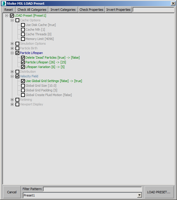
- The dialog will list any available Preset files in the drop-down list at the bottom.
- The Filter Pattern field can be used to filter the list to display only specific Presets on the list.
- If a valid preset is selected, the dialog will show a tree view with all supported rollouts and controls in them.
- If a control’s value stored in the preset matches the current value in the Stoke simulator, its entry will be unchecked by default.
- Only values that are different between the current object and the preset will be checked for loading, and will display the current value on the left and the file value on the right to show what changes would be made if the Preset is loaded.
- Unchecking the checkbox in front of a rollout will cause none of its controls to be loaded, regardless of their individual checkboxes.
- The color of the rollout title will be in blue when all its controls are checked, half-grayed out when only some controls are checked, and gray when no controls are checked. In the latter case, the tree branch of such a rollout will also be collapsed.
- Unchecking the root “LOAD Presets” entry checks/unchecks all top-level rollout entries too.
In the above screenshot,
- the Preset1 file contains different settings for all controls in the “Particle Lifespan” rollout, resulting in blue title and green entries with checked checkboxes. If the Preset is loaded, the Delete ‘Dead’ Particles checkbox will be unchecked, the Particle Lifespan value will be changed from 26 to 25, and the Lifespan Variation value will be changed from 6 to 5.
- The “Velocity Field” rollout only has one control that differs from the content of the Preset, hence the blue/gray title.
- The “Cache Options” rollout was originally collapsed because there is no difference between the current settings and the Preset’s content, but that branch was expanded manually before taking the screenshot.
- All other rollouts were collapsed by default because all their controls are already matching the Preset’s values.
Other Dialog Controls
The top of the dialog contains the following controls:
- Reset - pressing this button reinitializes the dialog to its original settings including checkbox states and expanded/collapsed branches. This is a shortcut for pressing Cancel to close the dialog and LOAD Preset to reopen it.
- Check All Categories - pressing this button will check the checkboxes of all top-level rollout entries.
- Invert Categories - pressing this button will uncheck the checked and check the unchecked rollout entries.
- Check Properties - pressing this button will check all checkboxes of all controls under the highlighted rollout.
- Invert Properties - pressing this button will invert the checked state of all checkboxes under the highlighted rollout.
- Search Field - entering a search pattern in the text field will highlight the entries that contain the given token. If the entry is inside a collapsed branch, the rollout’s branch will be expanded automatically to show the entry.
The SAVE Preset dialog
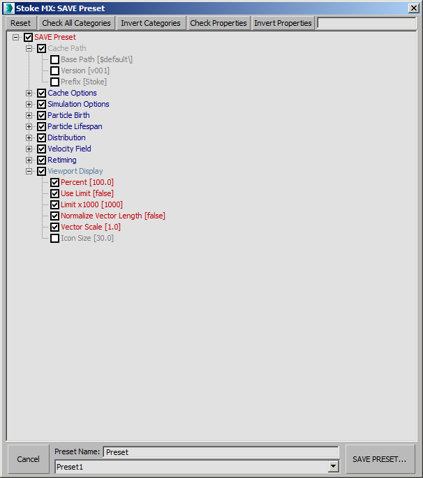
Pressing the SAVE Preset button opens a Stoke MX SAVE Preset dialog for saving the values of one or more UI controls to a UI Preset file.
- The dialog lists all supported rollouts and their controls.
- You can enter the name of the preset at the bottom, or select an existing preset from the drop-down list to populate the field and overwrite the existing file.
- The color of the rollout title represents the states of the controls in it - blue when all are checked, half-gray when only some are checked, gray when none are checked.
- When a rollout is unchecked, all its controls will be ignored and not saved.
- When a rollout is checked, only its checked controls will be saved.
- Each control line also shows the current value to be saved.
- By default, all controls under Cache Path rollout and the Icon Size under Viewport Display rollout will be unchecked because they should not be applied to other objects in most cases.
- Unchecking the root “SAVE Presets” entry checks/unchecks all top-level rollout entries too.
In the above screenshot,
- the tree was originally collapsed by default when the dialog was opened, but the Cache Path, Chache Options and the Viewport Display rollout branches were expanded manually to illustrate their content and color schemes.
- The Cache Path controls were all unchecked by default, so the title of the rollout was grayed out.
- The Cache Options controls were all checked. so the title was shown in blue.
- The Icon Size control in Viewport Display was unchecked by default, so the Viewport Display rollout was shown in blue/gray shade.