Geometry Meshing And Texture Map Blending
Introduction
The following tutorial digs deeper into the Geometry Meshing mode of FROST explored in the previous tutorial. It explores how to control the texture mapping on the resulting Geometry.
Texture Mapping Basics
Let’s create a very simple test scene containing a Plane primitive and a Teapot.
- Start a new 3ds Max scene.
- Create a Teapot with Radius of 5.0.
- Create a Plane primitive with Width and Length of 200.0 units and 20x20 segments.
- Without deselecting the Plane, create a FROST object, for example by selecting the top option from the Frost menu in the 3ds Max main menu bar.
- Switch the FROST Meshing mode to Geometry.
- Change the Particle Size > Radius value from 5.0 to 1.0 to preserve the origing mesh size of the custom geometry without additional scaling.
- Switch the Particle Geometry rollout’s top drop-down list to Custom Geometry.
- In the Custom Geometry group of controls, click the Pick button and click the Teapot in the viewport.
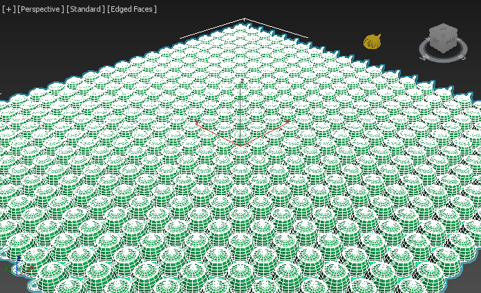
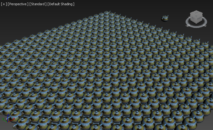
RESULT: The FROST mesh should distribute one Teapot mesh on every vertex of the Plane.
Mapping Coordinates Propagation
Let’s create a Standard Material with a texture map to explore how the texture coordinates of the Plane and the Teapot are being handled.
- Open the Compact Material Editor of 3ds Max.
- Select the first sample slot and click the Map button next to the Diffuse color swatch.
- Click Bitmap from the Material/Map Browser.
- Select any image file from your disk drive.
- Select the Teapot, the Plane and the FROST objects in the scene (or in the Scene Explorer).
- Assign the Material to all three objects.
- Enable the Show Shaded Material In The Viewport icon to display the texture in the viewports.
- Make sure Edged Faces display mode is off to see the shaded geometry in the viewport.
RESULTS:
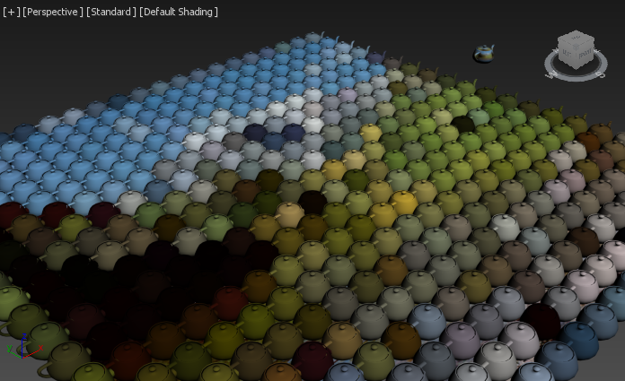
The FROST mesh has each Teapot colorized according to the texel at the vertex where the Teapot was placed, essentially turning each Teapot in an oversized texel! This is because the Mapping Coordinates of the vertices are propagated to the whole Custom Geometry meshes.
Hiding the FROST object shows the Plane with the full quality texture mapped using the Plane’s Mapping Coordinates in Channel 1.
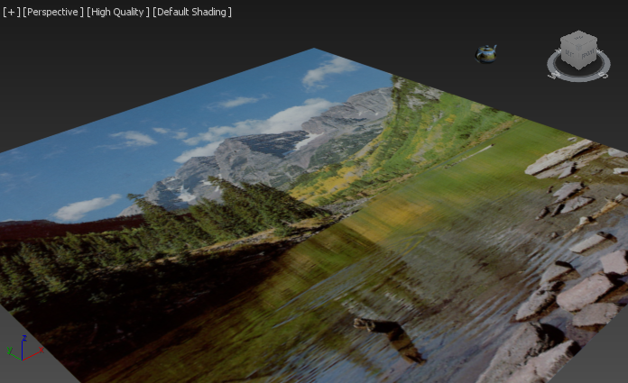
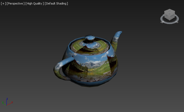
Looking at the Teapot primitive, the Texture is wrapped around it according to its own Mapping Coordinates in Channel 1.
IMPORTANT NOTE:
- As you can see from this test, when a Custom Geometry object has the same Mapping Coordinates channel as the Particle Objects (Mesh Vertices, Particle System etc.), the Particle’s Mapping Coordinates override the Custom Geometry’s Coordinates!
- If you need to access the Mapping Coordinates of the Custom Geometry mesh, you need to use a Channel that does not exist in the Particle Objects.
Accessing Mapping Coordinates In The Custom Geometry
Let’s see how we can map a texture on the Custom Geometry Teapots in FROST the same way as on the Teapot primitive.
- Select the Teapot primitive
- Switch to the Utilities tab in the 3ds Max Command Panel.
- Click on the More… button.
- Select the Channel Info utility from the list.
- Click the Channel Info button in the Parameters rollout.
- Select the last channel on the list (ID column, 1:map row).
- Click the Copy button to copy the channel.
- Click the Add button to add a new mapping channel, confirm the popup dialog.
- Select the new channel and press the Paste button to copy Channel 1 into Channel 2.
At this point, the Teapot has the same Mapping Coordinates data in both Channels 1 and 2.
- Open the Material Editor.
- Go into the Bitmap texture controls and change the Map Channel value from 1 to 2.
RESULT: The FROST mesh will now find a Mapping Channel 2 in the Custom Geometry Teapot mesh, but not in the particle source, and will thus retain it unchanged. Each Teapot in the FROST mesh now maps the texture like the original Teapot primitive!
Compositing Multiple Texture Maps
Keeping the above basic rules in mind, we could easily composite multiple texture maps, each one using different mapping coordinates.
Multiplying Two Textures
- Open the Material Editor
- Go to the Diffuse Map’s Bitmap texture level.
- Click on the Bitmap button to insert a new Texture Map.
- Select the Composite map from the Material/Map Browser dialog.
- Answer the dialog with Keep old map as sub-map and press OK
- In the new Composite map, click the Add A New Layer icon.
- Change the new layer’s mode from Normal to Multiply.
- Click the map button on the left of the new layer, add a new Bitmap map and pick the same bitmap texture from disk (or a different one if you wish).
- Change the new bitmap to use Map Channel 2.
- Hide the Plane since it has no valid Channel 2 and would otherwise cause a warning when rendering.
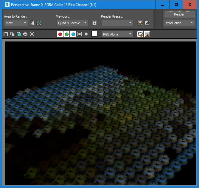
- Render using the Default Scanline Renderer to see the result.
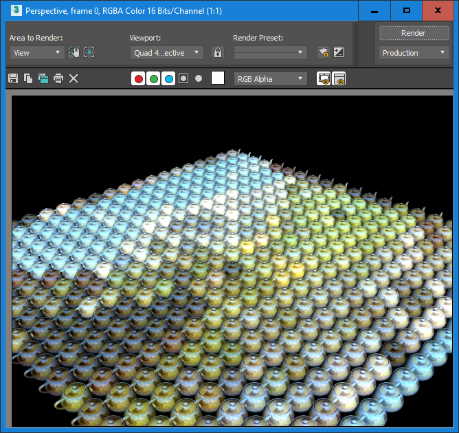
RESULT: The two versions of the texture, one evaluated at every vertex of the Plane, and one wrapped on the Teapot itself, are now multiplied.
NOTES
- The 3ds Max Viewports are unable to display the result of the Composite map, so the actual display might be misleading. This is why we use the production renderer to check the results…
- The same result above could be achieved with an RGB Multiply map, but it would be much less customizable - see below
Adding Two Textures
- Go up one level to the Composite map
- Change the top layer’s mode from Multiply to Addition
- Render again.
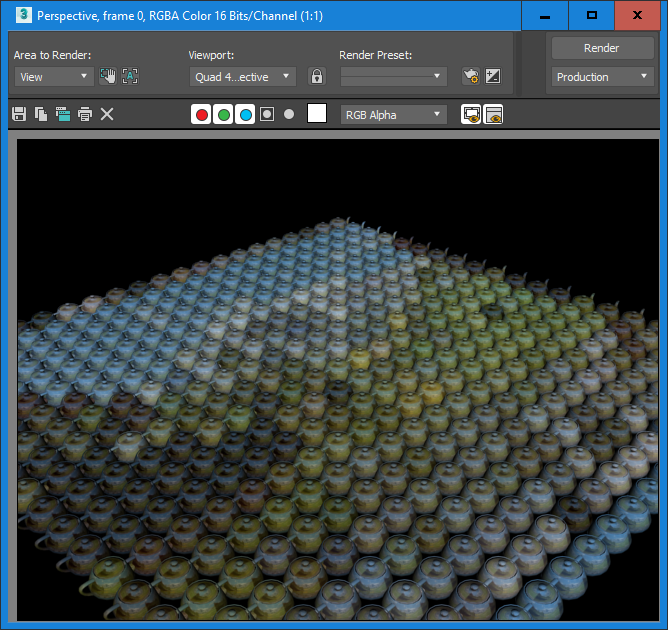
RESULT: The colors of the two textures are now added together:
Blending Two Textures
- Change the top layer’s mode from Addition to Normal
- Change the Opacity value of the top layer from 100.0 to 50.0
- Render again.
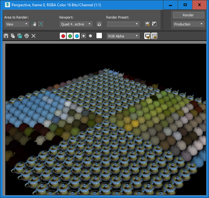
RESULT: The colors of the two textures are now blended together, 50/50. You can use all features of the Composite map to combine the two (or more) texture maps as needed.
Blending Complete Materials
Another approach to mixing textures is to combine two Materials within a 3ds Max Blend Material.
Blending With A Single Mix Amount Value
- Open the Material Editor
- Select an unused slot and create a new Blend Material, keep old material as sub-material.
- Go to the sub-material 1 level and click the Diffuse Map button next to the Diffuse color swatch.
- From the Sample Slots list of the dialog, pick the first Bitmap texture used in the previous examples (the one using Map Channel 1).
- Go up two levels.
- Go to the sub-material 2 level and click the Diffuse Map button next to the Diffuse color swatch.
- From the Sample Slots list of the dialog, pick the second Bitmap texture used in the previous examples (the one using Map Channel 2).
- Go up two levels.
- Set the Mix Amount to 50.0 to blend the materials half-and-half.
- Render in the Default Scanline renderer.
RESULT: The same image as the blending of two textures in the previous example will be rendered.
Blending Using A Mask Map
- Click on the Mask map slot
- Pick a Checker map - it will use Map Channel 1 by default, and will thus map to the Plane’s coordinates.
- Render again.
RESULT: Black color from the Checker map will reveal the first texture, white colors will reveal the second texture. You can of course use grayscale values to mix the two maps in different proportions.
Blending Using A Krakatoa Magma Flow
Using the Krakatoa MX PRT Source object in version 2.5 and higher, we can easily turn the vertices of the Plane to Krakatoa particles, and then control the exact mixing propotions by setting another Mapping channel and a Vertex Color map to pass its values into the Blend Material.
- Select the Plane object
- Select Create PRT Source object(s)… from the Krakatoa menu - a new PRT Source will be created.
- Select the FROST object, select the Plane object on the Particle Objects list and press the Remove button.
- Press the Pick button and click on the PRTSource_Plane001_001 object - at this point rendering would produce the same result as the previous test…
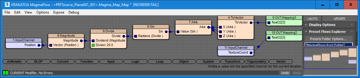
- Select the PRTSource_Plane001_001 object and add a Krakatoa Magma modifier.
- Set up the following Magma Flow

- Click on the Checker map in the Blend Material and replace it with a Vertex Color map.
- Set the Vertex Color map to use Map Channel 3.
- Render.
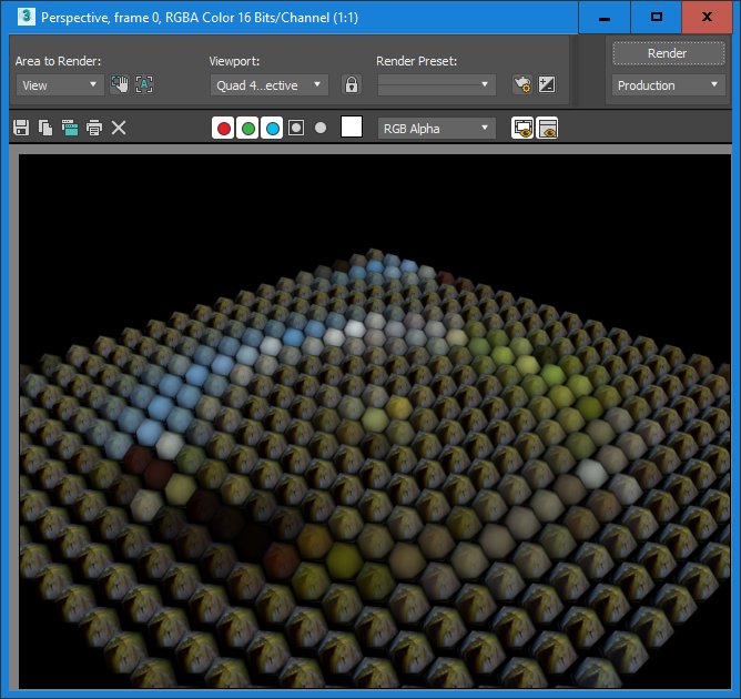
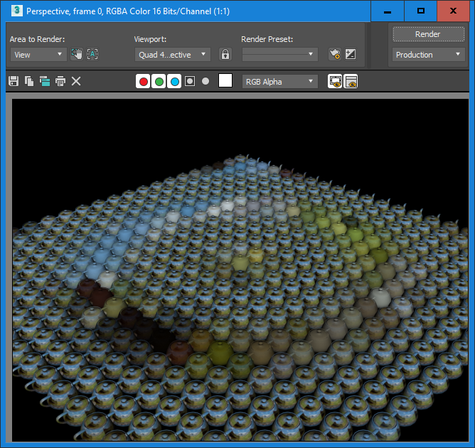
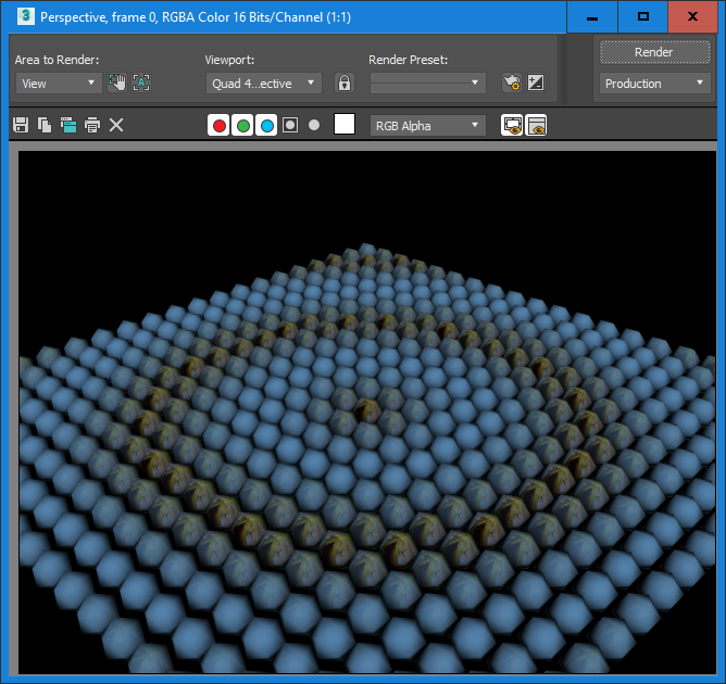
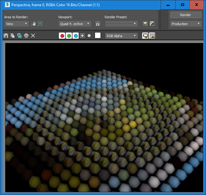
RESULT: The image will show a radial sine wave revealing the two textures in turn:
Built-In Geometry Shapes
The Exception To The Rule
In all previous examples above, we used a Custom Geometry mesh picked from the scene. However, built-in Geometry shapes like Plane, Box and Sphere behave a bit differently.
- Select the FROST object and switch the Particle Geometry from Custom Geometry to Sphere
- Try to render
RESULT: A warning dialog will appear telling you that UV Channel 2 does not exist in the FROST object. If you continue anyway, the following image will be rendered:
NOTE that other than with Custom Geometry, the Sphere shape retains its native Mapping Channel 1 coordinates, overriding the Mapping Channel 1 coming from the particles. The reason for this behavior is that specifically in Plane and Sprite mode, the user is more likely to want to map a sprite texture to the shape, so replacing the native coordinates with the ones of the particles would be undesirable in a larger number of cases.
The Solution
The solution in this case is very similar, except that we need to copy the Mapping Channel 1 into Mapping Channel 2 on the particles instead of the shape (since we have no access to the shape’s mesh anyway).
- Select the PRT Source and open the Magma Editor.
- Create a Mapping2 Output node and connect an InputChannel TextureCoord node to it. This will copy Mapping Channel 1 into Mapping Channel 2.
- Render again.
RESULT: This time, the texture from the Plane passed through the PRT Source will end up as Channel 2 on the Frost Spheres.
Since we used the exactly same texture in both blended materials, it does not matter much, however the Blend Material’s “waves” are now inverted.
We can fix this in one of three ways:
- Swap the materials in the two slots of the Blend Material,
- Change the Map Channel values from 1 to 2 and from 2 to 1 in the two textures while keeping the slots in the same order, or
- Invert the Mapping value going into Mapping Channel 3 in the Magma flow by adding a Subtract from 1.0 node behind the Abs operator.
In all three cases, the output would be this: