Geometry Meshing Mode
- Introduction
- Part 1: Meshing a Geosphere
- Orienting Camera-Facing Particles
- Random Orientation In Local Space
- Try the Other Modes Yourself
- Adding Custom Geometry
- Particle Orientation By Position Vector
- Particle Orientation By Normal Vector
- Using Multiple Custom Geometry Objects
- Preparing a PRT File
- Custom Channels Via MagmaFlow
- ShapeIndex By Volume Select
- Switching List Order
- Soft Selection And Shape Index
- Mapping Particle Parameters
- Part 2: Material Control
- Conclusion
Introduction
The following tutorial will familiarize you with some of the basic geometry meshing abilities of FROST.
In addition to generating metaball surfaces using various methods mentioned in the Particle Sources and Meshing Modes tutorial, FROST can also replace each particle in the source systems with a pre-defined or custom mesh.The main purpose of this feature is to allow post-processing of particles saved to disk as a Particle Sequence without the need to load and re-process in Particle Flow. A particle file sequence is history-independent. This way, the meshing of the particles can be decoupled from the particle simulation, speeding up both processes.
Part 1: Meshing a Geosphere
Let’s create a Geosphere primitive and use the Frost Geometry meshing mode to explore the basic settings before moving on to more advanced methods.
- Start a new 3ds Max scene.
- Create a Geosphere primitive with Radius 40 at Position 100,50,50
- Deselect the Geosphere, click the FROST icon and create a FROST object by clicking and dragging in the viewport (we do this because we want the Frost icon not to be centered at the Geosphere, and not to have the same wireframe color)
- In the Particle Objects rollout, click the Pick button and pick the Geosphere to add to the list.
- In the Modify Panel, change the Meshing mode to Geometry
RESULT: The FROST mesh will be switched to the default Geometry type - Planes. The main purpose of this mode is to create facing particles, similar to the Shape Facing operator in Particle Flow.
Let’s see how Facing Particles are controlled in FROST.
Orienting Camera-Facing Particles
In order to orient the particles, just like with the Particle Flow Shape Facing operator, we need a Camera or another reference object.
- With the Perspective viewport selected, press Ctrl+C to create a Camera from view.
- In the Particle Geometry rollout, locate the Orientation group and switch from Specify Orientation to Look At Target Object.
- Since the Target Object is not defined yet, all particles will look at the world Origin.
- Click the Target button and hit H to select the Camera by name, or click in a viewport to select it
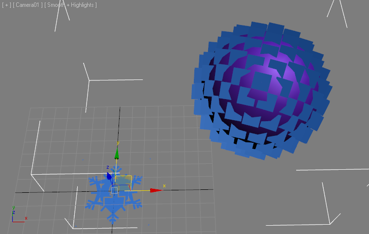
RESULT: All particles will be rotated to face the Camera’s position. The planes will not be parallel but will be rotated slightly, with the Z axis of each one of them pointing at the Target object.
Note that just like in Particle Flow, the Target Object does NOT have to be a Camera, it can be any 3ds Max scene object.
Of course, if you animate the Target Object, the particles will follow it throughout the animation…
FROST also supports the equivalent to the Particle Flow’s Use Parallel Direction - switch to Match Target Object and the particles will be oriented along the +Z axis of the Target Object:
Random Orientation In Local Space
Right now all particles are oriented the same. We can use the Divergence angle to introduce some random rotation.
- Enter a Divergence value of 180 - the planes will rotate randomly in 3D space.
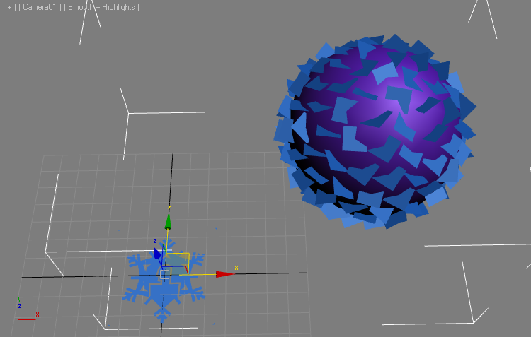
- Check the option Restrict Diverg. To Axis - the planes will be rotated randomly about the World Z Axis (which is the default setting for Divergence Axis restriction).
- Switch the drop-down list from World to Local
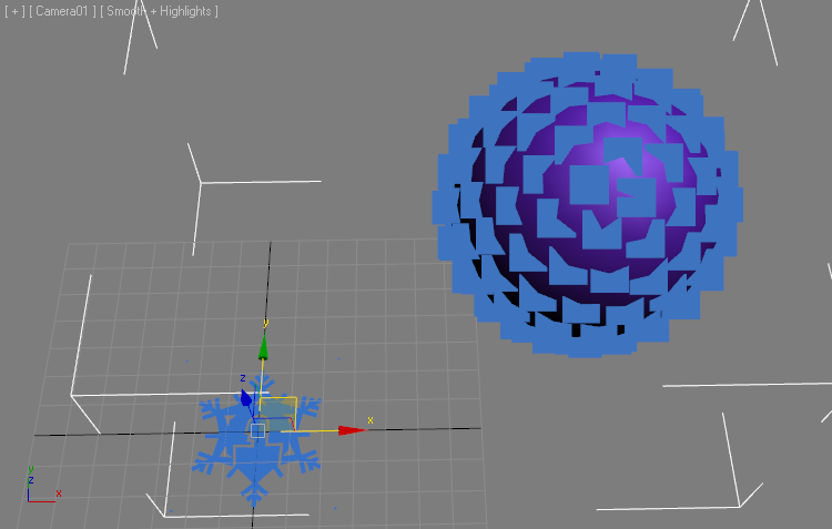
RESULT: The particles are now rotated randomly about their local Z axis, and since the local Z is parallel to the camera’s Z, they are thus rotated in image plane space!
Try the Other Modes Yourself
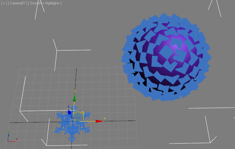
You can switch the Geometry type to one of the other options to check them out - Sprite is a combination of 3 planes crossing at 90 degrees, Tetrahedron, Box and Sphere produce simple volumetric primitives. Next, we will look at the most powerful mode - the Custom objects.
Adding Custom Geometry
Similar to the Shape Instance operator in Particle Flow, the FROST Custom geometry objects list lets you select one or more scene objects to use as the shape of the particles.
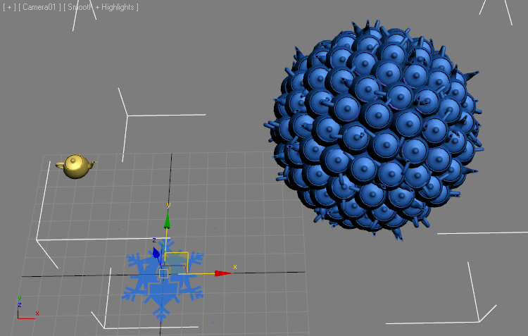
- Create a Teapot primitive with a Radius of 7.
- Change the Radius parameter of FROST to 1.0 to use the Teapot’s size as is.
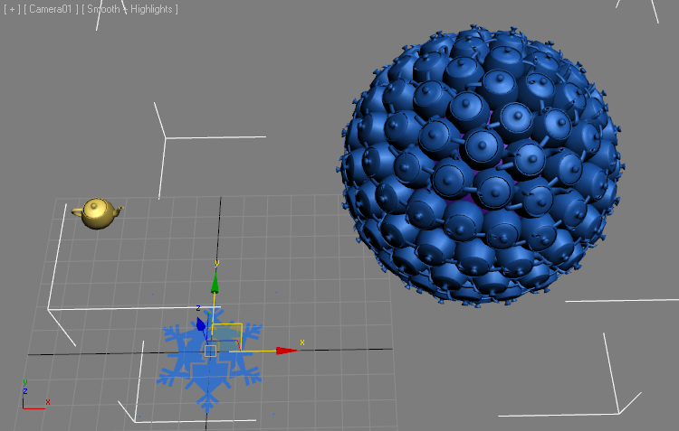
- Click the Pick button in the Custom Geometry group of controls and pick the Teapot from the scene
RESULT: All particles turn to Teapots. The Camera alignment and Divergence stil apply.
The Orientation of the particles can be set to a number of modes. Let’s take a closer look:
Particle Orientation By Position Vector
- Set the Divergence back to 0.0
- Switch the Orientation drop-down list to Use Vector Channel.
- The Vector Channel list will be set to Position by default (mainly because Position is a channel that is guaranteed to exist - no particle can exist without a Position!)
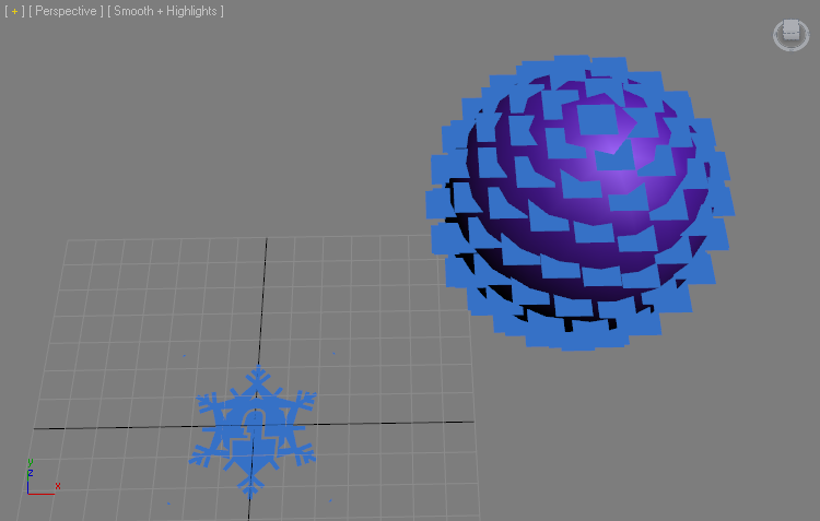
RESULT: The particles will be oriented to look away from the World Origin because the Position vector connects the world origin with the particle’s Position.
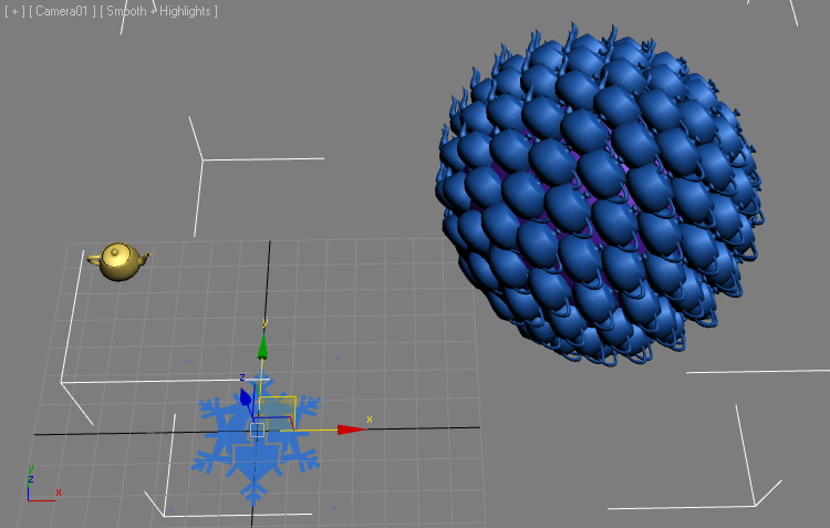
Particle Orientation By Normal Vector
- Switch Vector Channel from Position to Normal
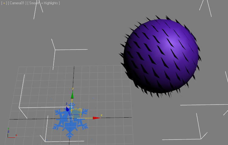
RESULT: The particles are now facing away from the surface along the Vertex Normals of the Geosphere.
The Normal channel is available from all geometry meshes, Particle Flows, Thinking Particles systems, Krakatoa PRT Loaders loading file sequences containing a valid Normal channel, Krakatoa PRT Volume objects and Krakatoa PRT FumeFX objects with Normals From Density Gradient enabled.
Some particle sources might not provide a valid Normal channel, in that case a value of [0,0,1] will be assumed, causing their particles to align to the world Z axis.
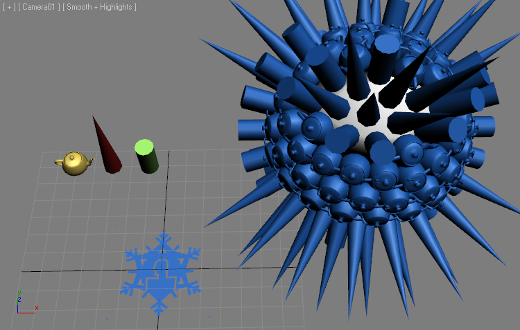
Using Multiple Custom Geometry Objects
- Create a Cone primitive with Radius 1 of 5.0, Radius 2 of 0.0 and Height of 50.0
- Set the Cone’s Sides to 8.
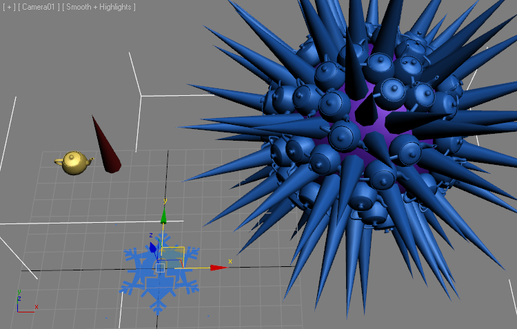
- Pick the Cone as a Custom Geometry object - the particles will be assigned the Teapot or Cone in order, because the default mode is Cycle Shapes.
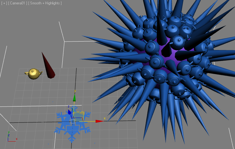
- Switch the drop-down list to Random Shape By ID - the distribution will change. Since the vertices have no real Born ID channel (only particle systems generate that channel), the vertex index will be used instead.
- Change the Seed - the distribution of the particles will change.
- Switching the distribution mode to Use ShapeIndex Channel will make the FROST mesh disappear because there is currently no such channel.
If you would open the Frost Log Window, you would see a message saying “ERR: BuildMesh: The particles don’t have a “ShapeIndex” channel, which is required when selecting instance geometry by ShapeIndex.”
To use the ShapeIndex channel, we must convert our Geosphere to a particle cloud using Krakatoa.
Preparing a PRT File
- Select the Geosphere, call Isolate (Alt+Q) to hide all other objects.
- Move the Geosphere to the origin 0,0,0
- Open the Krakatoa GUI
- Switch to Save Particles To File Sequence mode
- Specify a PRT file name to save to.
- Add TextureCoord to the list of channels to save.
- Enable the >Geo.Vertices source option.
- While on frame 0, press the SAVE PARTICLES button
RESUT: A single frame will default channels be saved to disk.
- Exit Isolation mode.
- Hide the Geosphere primitive
- Create a Krakatoa PRT Loader at position 100,50,50
- Pick the PRT file you just saved
- Check the Load Single Frame Only option
- Click the % of Render button and select 100.0
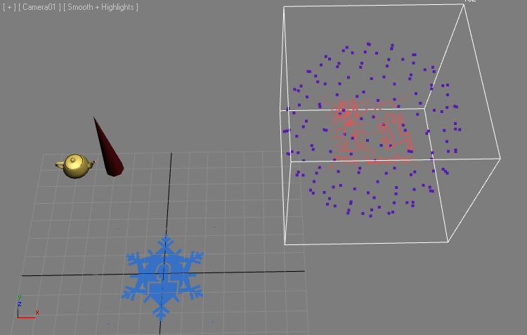
- In the FROST Particle Object rollout, remove the Geosphere and pick the PRT Loader.
RESULT: The PRT Loader now shows the vertices of the GeoSphere as particles, but the FROST still does not get a ShapeIndex channel.
Custom Channels Via MagmaFlow
- Select the PRT Loader and add a MagmaModifier to its stack.
- Press the Open Magma Editor button.
- Press [Ctrl]+[O] to create a new Output node.
- Switch the “Channel List Sorting” drop-down list to “Frost” mode - this will show only the channels relevant to controlling Frost features!
- Select the ShapeIndex channel from the list.
- Click once again on the Output node to select it and press the [2] key on the top row of the keyboard to create an InputValue node with an Integer value of 2. It will be connected to the Output node automatically. If it does not get connected (because the Output node was not selected properly), drag a connection from the InputValue node to the Output node.
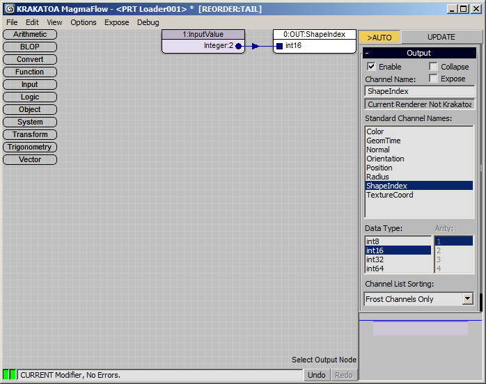
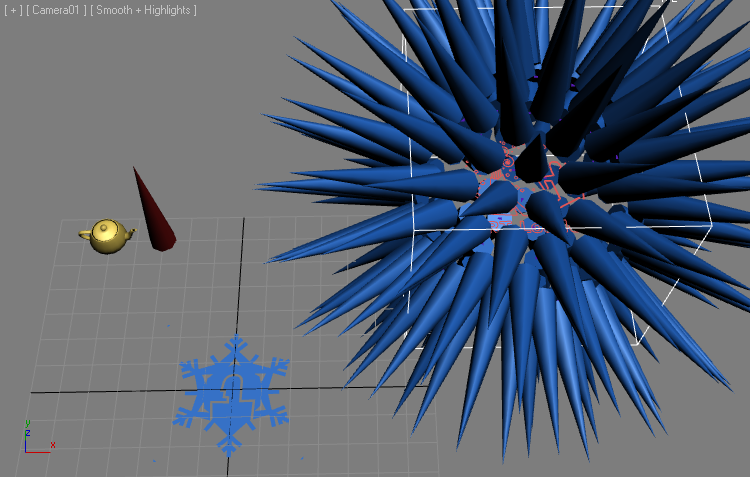
RESULT: All particles will now show the Cone shape because the ShapeIndex channel of each particle is set to 2.
ShapeIndex By Volume Select
- Add a Vol.Select modifier below the MagmaModifier.
- Switch to Vertex Mode, Sphere Gizmo. Go to Gizmo mode and move the gizmo to the side of the PRT Loader’s particle cloud.
- Open the Magma Editor and change the flow as follows:
- Switch the InputValue node to InputChannel and select the Selection channel from the list.
- With the InputChannel node selected, press [C] then [I] to insert a Convert > ToInt operator.
- With the ToInteger node selected, press [+] on the Numeric keypad to insert an Add operator.
- With the Add node selected, press [1] on the top keyboard row to create an Integer InputValue of 1.
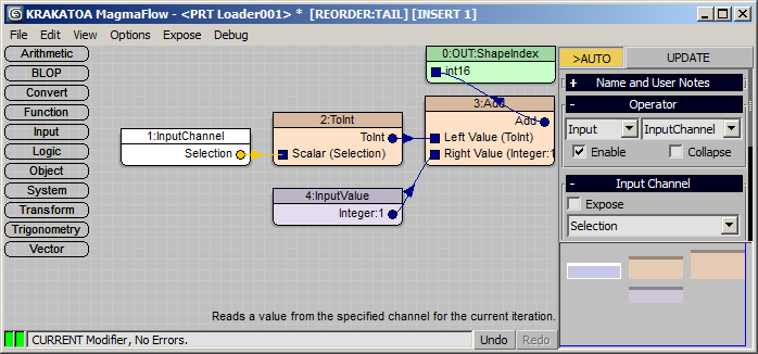
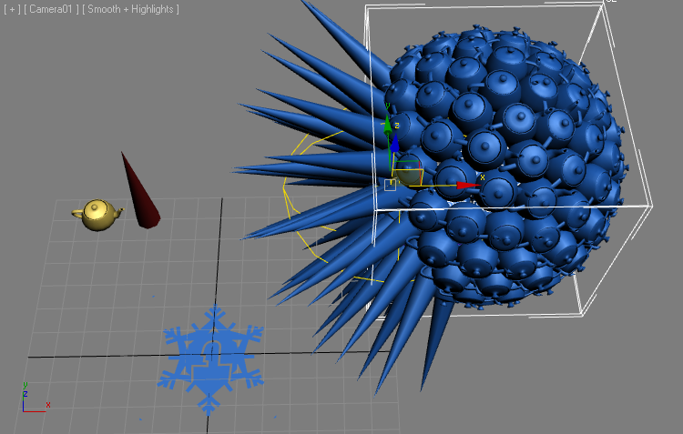
RESULT: The selected particles inside the Vol.Select’s gizmo get the second shape (cone), the unselected ones get the first shape (Teapot). This is because Selection channel contains 0 or 1, and 1 is added to produce ShapeIndex of either 1 or 2.
Switching List Order
Let’s say we want the opposite - selected should be Teapot and unselected Cone. We can either invert the selection of the modifier, or switch the order of the list. The former is easy, let’s see how the latter is done.
- Select the FROST object
- Press the [>>] button below the Custom Geometry list.
- From the menu, select the Sort item and pick Ascending Order - since the Cone starts with C which is before T, the list is sorted in opposite order.
- Press the [>>] button again and select Reverse Current Order - the list will be reversed to its original order.
Note that there are mutiple options to sort in various ways including creation order, object type, and of course manually moving objects up and down the list which can be very useful when working with more then 2 objects.
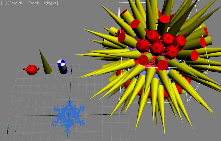
Soft Selection And Shape Index
- Create a Cylinder with Radius 5, Height 20, 1 Height Segment, 12 Sides.
- Pick as Custom Geometry in FROST
- Select on the list, press [>>], select Move Highlighted > One Object Up - now we have order Teapot, Cylinder, Cone and the FROST mesh shows Teapot and Cylinder only.
- Select the Vol.Select and enable Soft Selection. Set Falloff to 50.0
- Select the InputValue node and press [*] to insert a Multiply operator.
- With the Multiply node selected, press [Ctrl]+[2] to add a Float input with value 2.0
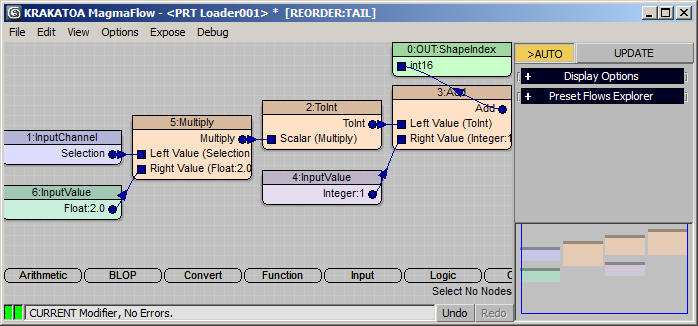
RESULT: The FROST mesh now uses 3 shapes - Teapot at selection of 0.0, Cylinder at 0.5 and Cone at 1.0.
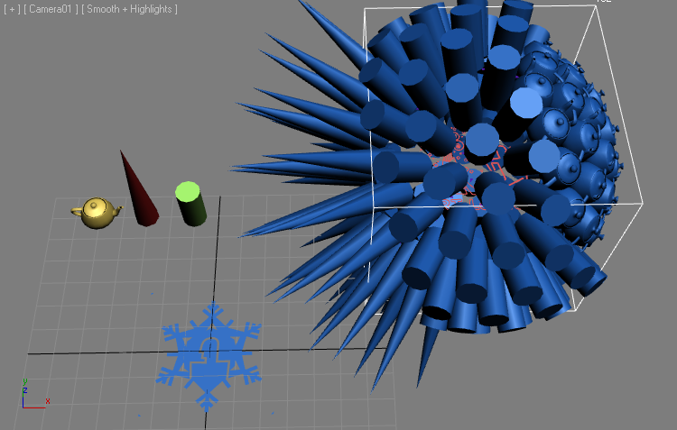
If you move the Vol.Select Gizmo around (or keyframe it to animate over time), the geometry assigned to the particles will change dynamically. While this is possible to achieve with Particle Flow, it is a lot easier using the Krakatoa PRT Loader / MagmaModifier / FROST combo.
Mapping Particle Parameters
When we saved the Geosphere to a PRT file, we also included the TextureCoord channel which contains the UVW Mapping Channel 1.
The image below shows the original Geosphere with a Standard Material applied for reference, showing the same texture map used in the Krakatoa Channels Modifier from the example below…
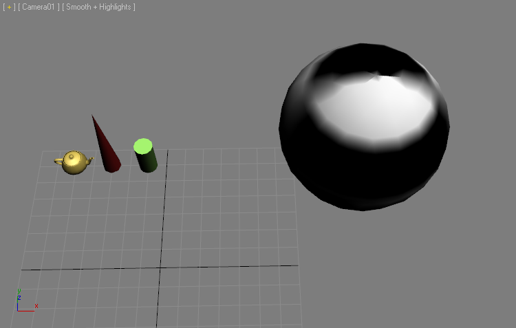
We could use a Texture Map set to use Mapping Channel 1 in a MagmaModifier on the PRT Loader’s stack and its texels will map to the particles just like they would map to the vertices of the Geosphere!
- Select the MagmaModifier and press the Open Magma Editor button.
- Select the InputChannel>Selection node and change its type to InputTexmap
- Press the Get Texture Map button and select a Checker Map
- Change the Texture Output Type to Mono (Float)
- Press the Put To MEdit button - this will open the 3ds Max Material Editor.
- Change the V Tiling to 2
- Change the Soften value to 0.1
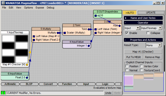
RESULT: The distribution of the geometry objects is now controlled by the Grayscale (Mono) value of the Checker Map - Cones on White, Teapots on Black and Cylinders on Gray.
Using a Krakatoa Channels Modifier, it is possible to sample the TextureCoord from the surface of any external geometry object (like the Geosphere). This could be used to acquire the mapping dynamically without the need to resave the PRT file with new mapping or even have a TextureCoord channel saved in the first place. But it is getting too deep into the realm of Krakatoa and MagmaFlow so we will stop here. If you want to know more about it, please post on the FROST or Krakatoa support forums.
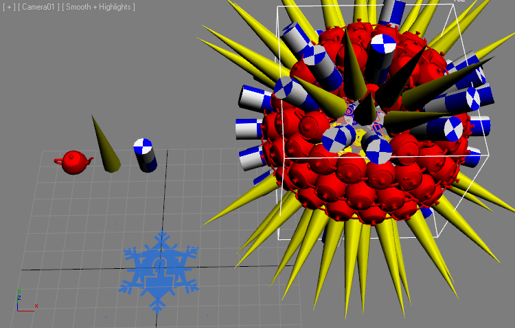
Part 2: Material Control
So far, we used the wireframe or vertrex color of the FROST object. It is time to take a look how it handles multiple materials potentially assigned to the various custom geometry objects.
Using Source Materials
Let’s assign some unique materials to the source geometry objects.
- Create a Standard Material with red diffuse color and assign it to the Teapot.
- Select the Cylinder and apply a UVW_Map modifier, set it to Cylindrical coordinates and Channel 2.
- Create another Standard Material with a Checker Map set to Blue and White, set to Channel 2 and assign it to the Cylinder.
- Create a third Standard Material with a yellow diffuse color and assign it to the Cone.
- Expand the Materials rollout of the FROST object and select the Material From Geometry option.
- Press the Create Material button
RESULT: A new Mutli/Sub-Object Material containing the materials assigned to the various geometry objects will be created and assigned to the FROST object. The Material IDs on the geometry faces will be combined and shifted up to avoid collisions. This will work correctly even if one or more of the Geometry Objects have a Multi/Sub-Object Material assigned.
The reason we used Channel 2 for the Cylinder is that FROST already sees and interpolates the Channel 1 from the particle object source (the PRT Loader). Thus setting the Checker map to use Channel 1 would result in a mapping based on the interpolated coordinates from the source and not the coordinates acquired from the Cylinder!
See the image below for an example of Channel 1 interpolation…
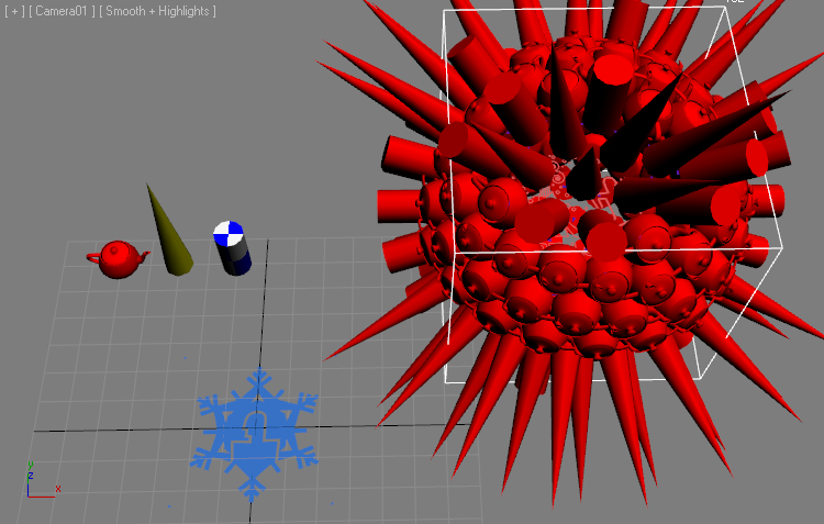
Single Material ID Mode
- Select the FROST object.
- In the Materials rollout, switch the drop-down list to Single Material ID
RESULT: The whole FROST object turns red. This is because all faces have Material ID 1 and our Multi/Sub Material has the Teapot’s red material in the first slot.
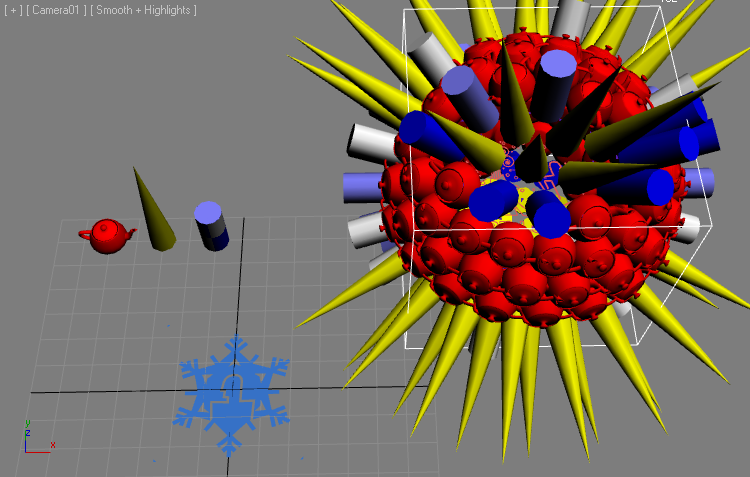
Material by MtlIndex Channel
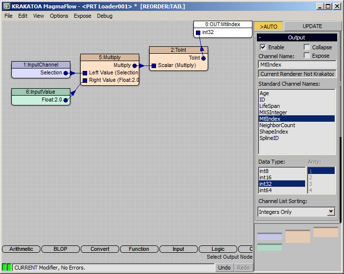
The MtlIndex Channel can be saved from Particle Flow and describes the material IDs of the particles. Since we have no such Channel in our PRT Loader’s PRT file, we can create it ourselves using a Magma Modifier. Let’s reuse the Vol.Select modifier’s Soft-Selection…
- Add a MagmaModifier to the PRT Loader.
- Wire a flow to read the Selection, Multiply by 2, convert to Integer and output as MtlIndex:
- Switch FROST to ID from MtlIndex Channel mode.
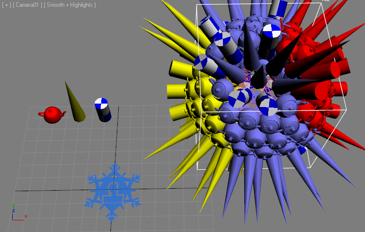
RESULT: The material assignment is now based on the Soft-Selection from the Vol.Select modifier - Yellow where the selection is 1.0, Blue/Checker where the selection is around 0.5 and Red where the selection approaches zero.
IMPORTANT: The MtlIndex channel is ZERO-BASED in Particle Flow, so it is ZERO-BASED in FROST, too!
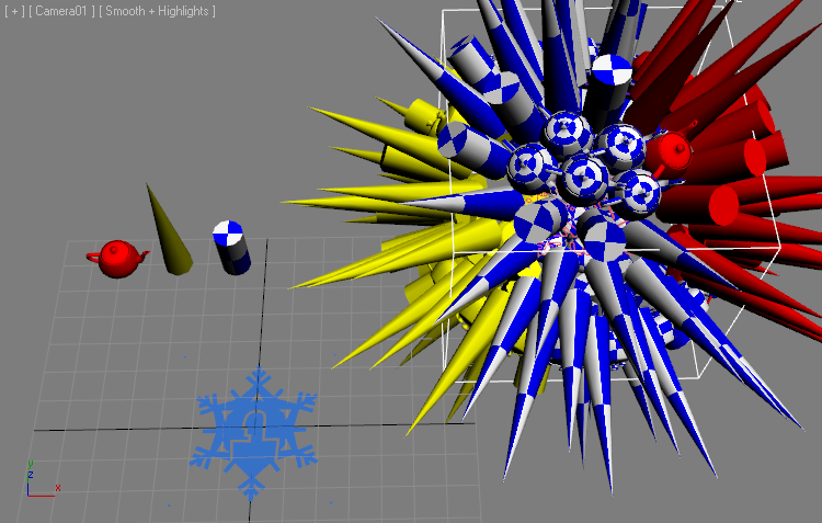
The Teapots and Cones appear blue because they have no Mapping Channel 2, while the Cylinders do. We could add a Channel 2 to them to show the correct mapping:
- Select the Cone and add an UVW_Mapping modifier.
- Switch to Cylindrical, check Cap, set to Channel 2.
- Select the Teapot - we will copy Channel 1 into Channel 2.
- Go to Utilities tab > More… > Channel Info and open the utility.
- Select the 1:map channel from the list and press Copy
- Press the Add button to add 2:map (Channel 2)
- Select the 2:map channel and press Paste
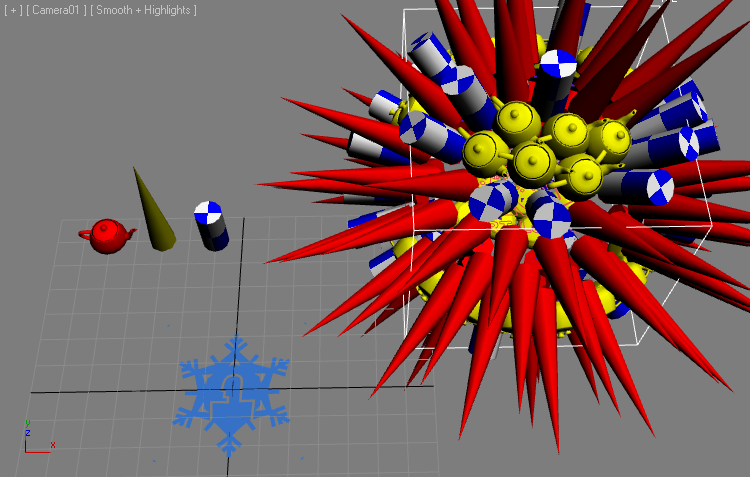
RESULT: Now both the Cone and the Teapot have a valid mapping Channel 2 and show the Checker map correctly.
Material ID By Shape Order
Yet another mode allows the assignment of Multi/Sub-Object Materials based on the Shape Numbers.
- Switch the Material mode to ID from Shape Number - the results will be the same as in the beginning because the Material IDs from the Shapes order and the Multi-Material order are the same.
- Now press the [>>] options button under the Custom Geometry list and select Sort>Ascending Alphabetical Order.
RESULT: The list will be now Cone, Cylinder, Teapot, with Cone having Material ID 1 (Red), Cylinder being 2 and Teapot being 3 (Yellow).
Material ID From Geometry
In this final mode, the face Material IDs of the Custom Geometry objects will not be changed at all by FROST - the Teapots have only Material ID 1, the Cones and Cylinders have Material ID 3 on the side faces, 1 on the top caps and 2 on the bottom caps…
Conclusion
In this tutorial, we looked as some of the FROST features related to replacing each particle with a custom geometry object. We only scratched the surface of what is possible, but you can apply these workflows to most particle sources, or expand on them in creative ways to get the desired results.
We also saw how saving the particle object to a PRT file via Krakatoa and using the PRT Loader together with Krakatoa Magma Modifiers opens completely new ways of controlling various parameters of the FROST mesher like Shape distribution, Material assignment etc.
In the next tutorial, we will look at the ability of Frost to control the particle geometry animation.
