Volumetric Rendering
Overview
KRAKATOA is a volumetric particle renderer.
Thus, understanding the concepts of volumetric rendering is very important for the correct use of its toolset.
Understanding Particle Density
The term Density is used heavily in the context of volumetric rendering.
- The virtual 3D space simulated by the 3D application is assumed void (completely empty) by KRAKATOA, except for areas where there are particles.
- Thus, light propagates through the empty space without being changed, unless when it comes in contact with particles.
- In that case, it can be attenuated through absorption, or diffused according to the selected shading model.
Note:
- The KRAKATOA renderer itself implements a feature that allows the user to assume the 3D space as non-empty, filled with a particpating medium that is not defined by particles. but either globally or using geometry volumes.
- This feature is called Ambient Participating Medium Extinction (APME) and is only exposed in KRAKATOA MX at this point.
- In the most general case, the word Density describes the amount of matter within a cubic unit of 3D space. Let’s call this Spatial Density.
- In addition, each particle carries a Density value describing the contribution of that particle to the Spatial Density at the region of space it is located in. Let’s call this Per-Particle Density.
- Particles in KRAKATOA are considered point-sized, so the Per-Particle Density carries the information about how the particle influences light that passes through the space occupied by the particle.
KRAKATOA provides two rendering modes - Particle (a.k.a. Point) rendering and Voxel rendering.
- The mathematics behind both modes use the same assumption - each particle carries its own Per-Particle Density that gets evaluated in space to produce the Spatial Density which affects light that passes through that space region.
- This applies to both light from the Light Source passing though particles, and light diffused by the particles passing to the Camera.
- Still, the two modes do not perform exactly the same calculations due to the different nature of their lighting and drawing algorithms. We will discuss this later in this topic.
The Density is thus reflected in the final rendered image by the amount of light attenuation (inter-particle shadowing), and by the Opacity of the rendered particles (as seen in the Alpha channel).
In other words, the Density in volumetric rendering is similar to (but not exactly the same as) the Opacity/Transparency in surface rendering.
Defining Per-Particle Density
In all versions of KRAKATOA, the following assumptions are made:
- By default, any particle generated without an explicit per-particle Density source will be assumed to have a Density of 1.0.
- If a particle is loaded from a PRT file sequence saved to disk, and the PRT file contains a Density channel, the saved value will be loaded as the initial per-particle Density value.
- If the particle is generated procedurally by a PRT Volume object, the per-particle Density will be based on the number of particles in a cubic unit spatial region. See Automatic Density Adaptation in PRT Volume further on this page.
- The per-particle Density of all scene particles can be overridden using the Global Overrides to enforce a uniform value that overwrites any changes made using the other methods discussed here.
- The per-particle Density is finally scaled by the KRAKATOA renderer during lighting and final particle drawing using the global Final Pass Density and optional Lighting Pass Density, allowing the adjustment of the overall Density level without touching the individual sources.
The various application-specific implementations of KRAKATOA make some further assumptions about the per-particle Density:
KRAKATOA MX in 3ds Max
- In KRAKATOA MX and KRAKATOA MY, the Density channel can be set or scaled using a Magma modifier assigned to the particle source.
- The Density channel can be set or scaled using a Magma modifier assigned to the particle source.
- The Opacity channel of a 3ds Max Standard Material assigned to the particle source will always scale the incoming Density value, e.g. setting Opacity to 50% will halve the per-particle Density.
- The KRAKATOA Material can be used to scale the incoming per-particle Density value.
- The Object Visibility value of any 3ds Max node will scale the incoming per-particle Density value.
KRAKATOA MY in Maya
- KRAKATOA MY makes the assumption that the OpacityPP attribute of Maya particles represents the Per-Particle Density value of the particle.
- The Density channel can be set using a Set Float Channel modifier.
- The Density channel can be scaled using a Scale Channel modifier.
- The Density channel can be set or scaled using a Magma modifier assigned to the particle source.
KRAKATOA C4D in CINEMA 4D
- The Density channel of a particle source can be set to a fixed constant value using a Set Channel tag <../kc4d/reference/kc4d_channel_ops.html#channel-set>`_.
- The Density channel of a particle source can be scaled using a Scale Channel tag.
- The Density channel of a particle source can be set based on a texture map using a Texture Channel Override tag.
- The Density channel of a particle source can be set based on another channel using a Channel Gradient tag.
Scene Scale Influence On Density
The Per-Particle Density value is expressed as Density per cubic scene unit.
- If a particle with a Per-Particle Density of 1.0 is the only particle within a cube with size 1.0x1.0x1.0 scene units, the Spatial Density of that region of space will be also 1.0.
- If 10 particles with Per-Particle Density of 1.0 are found in the same region of space, the Spatial Density would be of course 10.0.
This implies that the scene scale (or the assumptions about what a scene unit represents in real world) has a significant influence on the actual volumetric rendering.
- In other words, the size of your particle systems does matter because differently sized point clouds would occupy different volumes.
- If the same amount of particles carrying the same per-particle Density is distributed within a larger volume, the resulting Spatial Density will be obviously lower!
- This would require either
- more particles to be created within the larger volume,
- the per-particle Density to be increased while keeping the same count.
Increasing the particle count makes a lot of sense when rendering in Particle mode and rendering a close up of the particle cloud.
- If the camera comes too close, the individual points will start becomming apparent.
- In this case, adding more particles is a good idea.
Increasing the per-particle density is the better approach when the particle cloud is seen from the distance and its particles are allready covering the final image’s pixels adequately, but the contribution of their per-particle Densities is not enough to block enough light.
- In theory, in this case increasing the particle count and increasing the per-particle Density should have approximately the same effect.
- But the latter method would be much faster (loading and rendering less particles is obviously faster).
When rendering in Voxel mode, the per-particle Density values of all particles falling within a voxel are accumulated as the Density value of the Voxel itself.
- Thus, adding more particles or increasing the existing particles’ own Density should have exactly the same effect.
- Again, the latter approach will be faster because it would reduce the loading particles overhead.
Tweaking The Density At Render Time
To allow the easy tweaking of the resulting Spatial Density calculated by the renderer, KRAKATOA exposes global Density Scale controls.
There are two sets of controls - one for the Final Pass Density and one for the Lighting Pass Density.
- By default, the Final Pass Density is used for both the Lighting and the Drawing passes.
- Decoupling the two can be very helpful to achieve the desired look.
These controls multiply all particles’ Density values at render time, so the same simulation can be rerendered with different Density settings very easily without adjusting the individual particle sources.
The User Interface representation of these values employs two value fields - one for the Base value and one for the Exponent value. This lets the user change the Density by orders of magnitude much easier, and also facilitates a more convenient representation of very large and very small values without using too many zeros. For example, instead of typing in 0.0000000001, the user can enter 1.0 and -10 for the Exponent. Changing the -10 to -5 produces quickly 0.00001 and so on. Using positive Exponents produces very large numbers.
Automatic Density Adaptation in PRT Volume
The PRT Volume object of KRAKATOA performs some additional density calculations to keep the resulting spatial density constant.
- If you create one particle per region without any subdivisions and the Spacing is set to 1.0, the resulting particles will all have a Density value of 1.0 (because there is one particle in each cubic unit of space).
- If you reduce the Spacing to 0.1, there will be 10x10x10 particles within a unit cube, so the Per-Particle Density will be reduced by 3 orders of magnitude to 0.001.
- The same applies to using the Subdivide Region feature, and the Multiple Per Region option.
- In other words, when the PRT Volume creates more particles within a cubic unit of space, the multiple particles get a fraction of the density that a single particle would get when placed in the same volume.
- This way, increasing the particle count refines the lighting and rendering result, but does not increase the Spatial Density - generating 1000 times more particles does not produce 1000 times more Density inside the filled volume!
Scene Scale And Density Example
Let’s take a look at some actual scenes (using KRAKATOA MY in Maya in this case) to see how the above concepts work in practice.
We will start with a very simple setup:
- A Polygon Sphere with Radius 2 is created at the World Origin 0,0,0
- A PRT Volume is created from it with Spacing of 0.1 and 3 Subdivisions.
- A Spot light with Cone Angle 30 is created at 0,0,10 to illuminate the particles
- A Camera is created at 10,0,0 and rotated at 0,90,0 to look at the particles
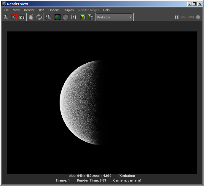
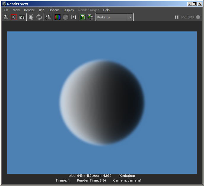
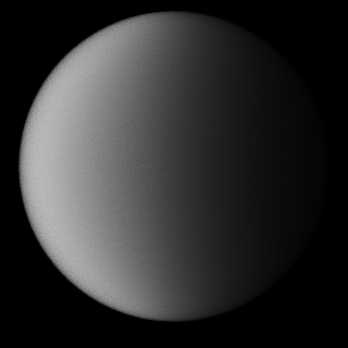
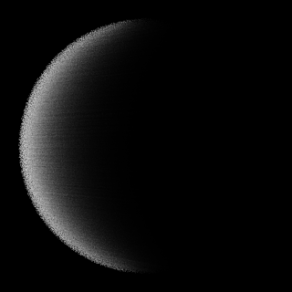
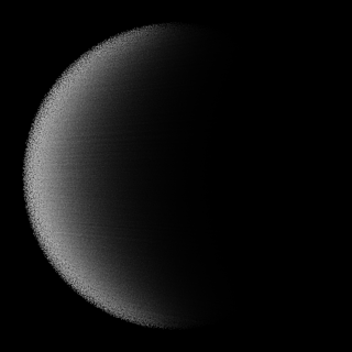
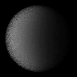
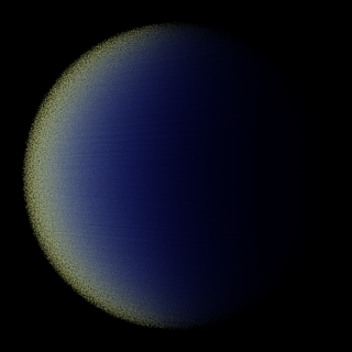
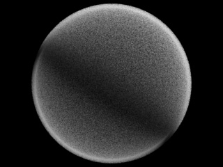
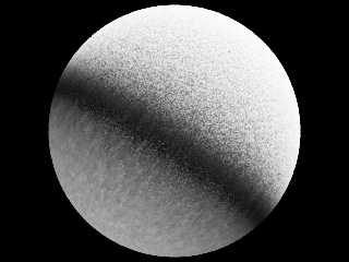
- Rendering with Final Pass Density of 1.0E0 (basically Density Scale of 1.0) produces the following image:

This image contains about 2 million particles and you can clearly see the light being slowly attenuated from left to right as it passes through the spherical cloud.
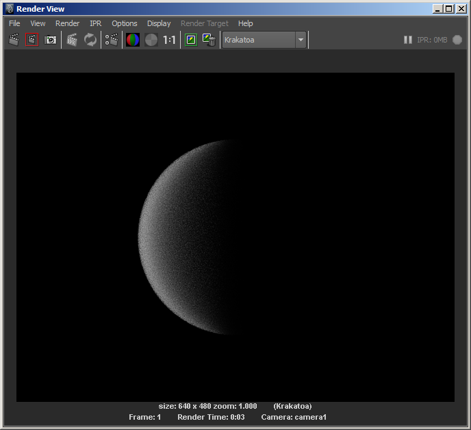
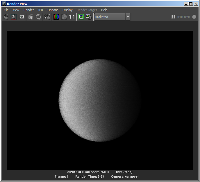
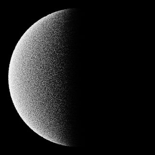
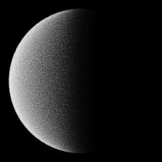
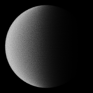
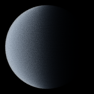
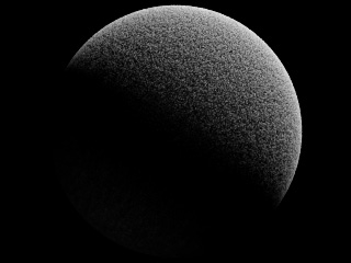
We could increase the Final Pass Density value by one order of magnitude to 1.0E1 (which means a multiplier of 10.0).
The resulting image shows that when we increase the Density 10 times, a lot more light will be blocked and the shadow on the right side will be deeper. But this also increases the density as seen by the Camera, so the individual particles become too solid and we start getting a grainy image.
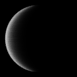
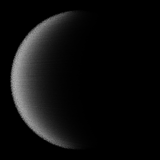
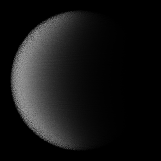
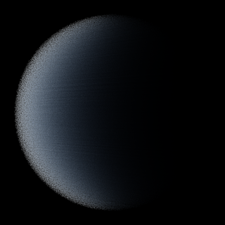
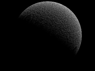
We can decouple the Lighting Pass Density and the Final Pass Density by checking the Use Lighting Pass Density checkbox. Now we have the 1.0E1 for Lighting to get a deeper shadow, but 1.0E0 for the Final (Camera) Pass to have a smoother surface:
Let’s save the PRT Volume’s particles to disk using the PRT Saver tool.
- Press the PRT SVR icon.
- Double-click the PRT Volume name to move it to the right column.
- Switch to Current Frame and One Sequence.
- Enter “SmallVolume” in the Sequence Name Prefix field.
- Uncheck the Velocity and ID channels, leave Color and Density checked.
- Press the SAVE PARTICLES… button.
This gives us a snapshot of our current PRT Volume. We will load it using a PRT Loader and scale it 10 times to see how this will affect the final rendering.
- Delete the PRT Volume object.
- Increase the Sphere’s Radius from 2.0 to 20.0.
- Move the Spot light from 0,0,10 to 0,0,100.
- Move the Camera from 0,10,0 to 0,100,0.
- Create a PRT Loader by pressing the PRT icon in the KRAKATOA shelf.
- Press the Load PRT File… button.
- Pick the file saved in the previous step from the PRT folder of the current project, subfolder v001.
- Check the Single File Only checkbox.
- Scale the PRT Loader 10 times to 10,10,10 - since it is loading only 1% of the particles, it will fill only a fraction of the sphere in the viewport, but it will render all particles at render time.
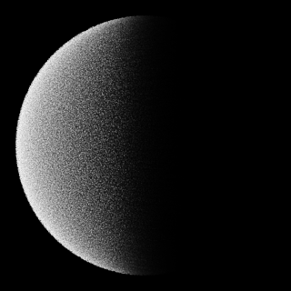
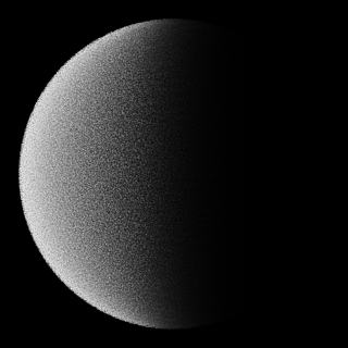
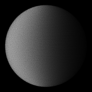
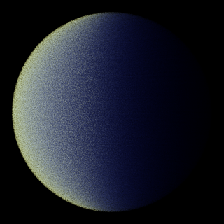
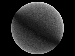
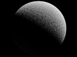
- Uncheck “Use Lighting Pass Density” and render with Final Pass Density of 1.0E0
Obviously we scaled the particle cloud up so we now have 1000 times more volume to cover with the same particles. The density is so low the Alpha is almost completely transparent.
Common logic would dictate that we should increase the Final Pass Density Exponent by 3 orders of magnitude from 0 to 3. But in practice this is not right - here is the result to prove it:

The above looks exactly like the rendering we did with Final Pass Density of 1.0E1.
But if we would reduce the Exponent from 3 to 2, we get what we expected:

Why is there a discrepancy of one order of magnitude?
- The KRAKATOA renderer itself applies its own Density remapping algorithm when calculating the relationship between image pixels and the volume that they represent.
- It is considering the density of all particles that lie behind a pixel and their contribution to a unit volume.
- As the camera is moving closer and farther from the particles, the contribution of the particles to a pixel is adjusted to produce consistent Density.
So as a rule of thumb, if we increase the size of our scene 10 times, we have to increase the Final Pass Density Exponent 100 times (two orders of magnitude) to produce the same result when rendering in Particles mode.
Scene Scale And Voxel Mode
The above does not apply to the Voxel mode though.
- In Voxel mode, the Densities of the particles are collected in an actual voxel grid.
- When the scene scale is increased 10 times, the accumulated Density is actually 1000 times lower.
- So in Voxel Mode, the Lighting and Final Pass Densities have to be compensated by 3 orders of magnitude.
Note that the Volumetric shading of Particle Mode and Voxel Mode are performed differently and do not produce exactly the same results using the same settings.
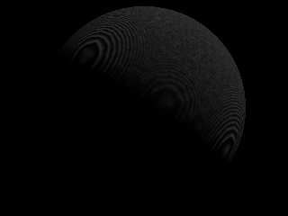
- Below is the rendering of the sphere with Radius 2.0 converted to PRT Volume.
- Final Pass Density was 1.0E-1 (because 1.0E0 is too dense for the Voxel mode).
- Voxel Size was 0.1 and Voxel Filter Radius was 1:
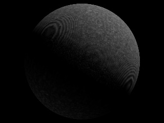
- And here is the PRT Loader scaled up 10 times in the larger scene, rendered with Final Pass Density of 1.0E2 (3 orders of magnitude higher) and Voxel Size of 1.0 - the two are IDENTICAL!
Scene Scale And PRT Volume
As mentioned earlier, the PRT Volume performs its own internal Density rescaling when creating particles.
- Changing the Spacing, Subdivisions, Multiple Per Region etc. are all taken into account to produce consistent Densities without the need to compensate manually.
- Below is the rendering of a Sphere with Radius 20.0 converted to PRT Volume with Spacing of 1.0, rendered in Voxel mode with Voxel Size 1.0 using Final Pass Density of 1.0E-1:

- Once again we get the exactly same rendered output, but we did not have to increase the Final Pass Density at all!
- The PRT Volume took care of it by itself - since the Spacing was increased 10 times from 0.1 to 1.0, the Density of the generated particles was also scaled up 1000 times.
- When rendering the same PRT Volume in Particles Mode though, there will be one order of magnitude difference since the already discussed volume-to-pixels remapping does not work exactly like the Voxel Mode.
- Since the PRT Volume itself scales the Per-Particle Density up 1000 times, we have to scale down by one order of magnitude to produce 100 times higher Final Pass Density than in the small scene.
- Here is the rendering with Final Pass Density of 1.0E-1:
In short:
- A PRT Volume from a mesh scaled up 10 times rendered in Particle Mode requires 10 times lower Density multiplier to compenstate the 1000x automatic increase.
- A PRT Loader scaled up 10 times rendered in Particle Mode requires 100 times higher Density multiplier due to the particles-to-pixels remapping.
- A PRT Volume from a mesh scaled up 10 times rendered in Voxel Mode requires no Density changes due to the automatic adaptive density feature of the PRT Volume.
- A PRT Loader scaled up 10 times rendered in Voxel Mode requires 1000 times higher Density multiplier to compenstate the 10x10x10 volume expansion.
Automatic Density Adaptation in PRT Volume Example
As discussed previously, the PRT Volume scales the Per-Particle Density of its particles as we increase the particle count to produce finer particle clouds.
Here are some examples of the same PRT Volume with Spacing of 1.0 made from the same 20.0 units Sphere used in the above examples, but using various Subdivision settings:
|
|
| No Subdivisions, 33,412 particles. | 1 Subdivision, 267,363 particles. |
| Render time: 0.312s | Render time: 0.717s |
| Too few particles to attenuate light. | |

|

|
| 2 Subdivisions, 902,455 particles. | 3 Subdivisions, 2,139,042 particles. |
| Render time: 1.248s | Render time: 2.184s |

|
|
| 4 Subdivisions, 4,177,927 particles. | 5 Subdivisions, 7,219,084 particles. |
| Render time: 3.635s | Render time: 5.631s |
Light Attenuation - A Look Inside
As mentioned in the beginning, the Per-Particle Density affects the light passing through the space where the particle is located by absorbing a fraction of the light’s energy.
- In the simplest case (with default KRAKATOA settings), the three components (R,G and B) of the light are affected equally.
- Assuming both light and particles are white, this produces a gray shadow that fades into black once all light has been absorbed after passing through many particles with enough Density.
We saw already what the spherical particle cloud looks like when the Density is scaled via the Lighting Pass and Final Pass Density multipliers. But it would be much more interesting to peek inside the cloud and watch the light’s distribution through the core of the sphere.
- Thankfully, this is very easy to achieve by simply creating a Polygon Plane object passing through the center of the Sphere and tagging it as a Matte (aka Occlusion or Holdout) object.
- After checking the Enable Matte Objects option in the Matte Objects panel and the Save Occluded Particles Pass in the Render Output And Passes panel, we will produce two rendered images - one containing all particles in front of the plane, and one containing the slice of all particles behind the plane!
- Here are the two slices using different Final Pass Density multiplier settings (also used as Lighting Pass Density, thus affecting the Light Attenuation).
- The left column shows the foregound particles, the right column shows the background slice and thus reveals what is happening inside the spherical cloud:
- The Densities from top to bottom are 1.0E0, 5.0E-1, 4.0E-1, 3.0E-1, 2.0E-1 and 1.0E-1:
Using Absorption
In all the tests above we used white light passing through white particles with uniform Absorption in all three components (RGB).
- Now let’s see how the Absorption option changes the Attenuation as the same white light passes through the same particle cloud.
- First we will use pure white light passing through particles with Absorption of 0.2,0.1,0.0.
- This means that the Red channel will be absorbed twice as much as the Green channel, and the Blue channel will not be affected at all.
- As result, the initially white particles will start losing their red first, then the green until left with only the Blue component in the deeper shadow regions:
- Let’s change the particle color from white to pale yellow (1.0,1.0,0.5) via the Override Color controls in the Global Render Values panel.
- This is quite unnatural because in nature a material that is producing diffuse component of yellow is most probably absorbing the blue component of light.
- But here we are both absorbing the Red and Green parts of the light’s energy, and reflecting the Red and Green components of white light back into the camera.
- The result is thus not necessarily physically correct, but it looks interesting regardless:
Shading Surfaces as Particles and Fighting the Moire Patterns
As mentioned already, KRAKATOA is a volumetric renderer. It is normally not used to shade thin surfaces like most other renderers, and of course this results in a different workflow.
It is important to keep this in mind when attempting to shade surfaces made of particles - when all particles are more or less co-planar without any particle cloud thickness - the lighting and self-shadowing algorithm can produce artifacts similar to the moire effects you would get if rendering polygons with shadow maps and a Bias of 0.0. In that case, the polygons would be exactly at the interface between light and shadow and only the numeric precision of the software would decide whether a point will be seen as lit or in shadow - theoretically, a point at the border between light and shadow is in neither, but practically the renderer has to pick a side, and it picks it after a certain numeric pattern, which results in the regular pattern seen on the surface.
- When a particle cloud has thickness, light is attenuated when passing through particles based on their density.
- This causes less light to reach particles that are behind the other particles, then the light is gradually attenuated again and again.
- At a certain depth inside the volume, it can be completely extinguished.
- The result is a nice sub-surface light bleeding which is typically desirable because that is how light behaves in the real world when penetrating particulate matter like dust clouds or smoke.
Note that the rendered image and attemuation map resolutions play a role when determining the density:
- KRAKATOA draws each particle as a point covering only a few pixels.
- Thus rendering at higher resolutions can cause a particle cloud to appear less dense to the light or camera.
- Zooming in and out in the same scene can make the same cloud appear more or less dense.
- This is somewhat consistent with the way particulate matter would appear in the real world
- If you move inside a sand storm, you would see single particles flying around you and lots of gaps between them.
- Looking at the same cloud from a large distance would make it appear more or less solid.
The Problem
The following simple KRAKATOA MX example uses
- A Geosphere with 10 segments
- A 3ds Max Particle Flow distributes 1 million particles on the Geosphere’s surface without any offset.
- A direct light illuminates the sphere.
The next image was rendered with the default density of 5.0 * 10^-1 (values of 5.0 and -1 in the KRAKATOA GUI, which represents 0.5):
As expected, this produces a very pronounced moire effect caused by self-shadowing particles at the border between light and darkness. The surface of the particle cloud facing the light source is shaded really dark because the particles on the surface are too dense (attenuating the light a lot) and at the same time often fall in their own shadow and receive no light at all.
Reducing the Density by an order of magnitude down to 0.05 reduces the effect but does not fix the problem completely - because the particles are less dense, their shadow is also less dense. Thus, the light is not extinguished completely and even particles that fall in their own shadow get the remaining portion of it:
Reducing the Density once again down to 0.005 removes the moire pattern, but this is at cost of no shadow casting from the upper right particles onto the bottom left particles - the backside of the sphere is lit almost identically to the side facing the light because the density is too low and light can pass through the particles without much attenuation:
The Solution
Instead of creating all particles at the same surface without providing the particle cloud with any thickness, let’s add an offset to the particles relatively to the surface.
- In the Particle Flow > Position Object operator, there is an Offset option.
- Using the default -1/1 values, let’s render at density of 0.005 again:
- In this case, the light still penetrates the complete sphere, but there is a visible thickness to the particle “shell”.
- Thus, increasing the particle density to 0.05 leads to a rather pleasant result:
- Going even higher to a density of 0.5 does not improve the result.
- The light is attenuated within the very top of the particle cloud and some artefacts can start appearing at the sides again:
So at a render resolution of 320x240 and 1M particles with 0.05 particle density, we have an acceptable result.
Controlling Lighting Pass Density Separately
As we already know, the KRAKATOA user interface lets us specify different density for the light attenuation calculations and for the final pass rendering.
- The following is the result of calculating the Lighting pass using a density of 0.05 while drawing the Final pass using a density of 0.5
- The shadows will be less dense, while the particles will still be rendered as relatively opaque.
- It combines the “hardness” of the surface appearance shown by the Density of 0.5 in the above example while retaining the illumination intensity of the 0.05 density example:
- Using even less density for the Lighting pass causes more light to leak through the surface and illuminate the back side of the sphere, while still shading as a rather dense point cloud:
- In 3ds Max, a similar effect can be achieved by keeping the global density to 0.5 for both passes by reducing the Shadow Density value in the light
- This allows for per-light tweaking of shadow / light attenuation calculations in KRAKATOA MX, but is not supported in other KRAKATOA implementations.