First Steps - Loading And Meshing A Point Data File
Overview
- The main function of SEQUOIA is the generating of a mesh from a point cloud.
- In the following tutorial, we will go through the basic steps involved in the loading and meshing of a point data file.
Considerations
- SEQUOIA requires you to convert various point file formats to its own spatial point data format (SPRT) which is very compact and supports fast loading of multi-billion points data files, multiple Levels Of Detail etc.
- Point Data files come in two major format variations - Text files (for example PTS, XYZ, CSV, TXT), and Binary files (for example PTX, E57, LAS etc.).
- Binary files typically contain metadata describing the data channels, units and more and can be converted to SPRT much easier.
- In this first tutorial we will look at loading a Binary file.
- Working with Binary files is recommended as they are faster, smaller, and easier to convert - if you have a choice when producing the data using a LIDAR scanner or 3rd party point cloud processing software, you should opt for one of the supported Binary formats.
Loading A Binray Point Data File Into SEQUOIA
- In this example, the source happens to be in the .e57 file format containing the LiDAR scan of a demolition derby car.
- In SEQUOIA, each Point Data Source is managed by a dedicated Scene Object called a Point Loader.
Creating A Point Loader
![[G]](../../_images/SQ_DOCS_GreenArrow_161.png) Click on the left-most green icon of the SEQUOIA toolbar:
Click on the left-most green icon of the SEQUOIA toolbar: 
- When a Point Loader is created, it will assume that you want to load a file from disk, so it will present you with a File Open Dialog for all supported Point Data file formats.
Navigate to the folder with the source file, and pick the one you want to load - in this example, it is the file ”.e57”.

Previewing The Point Data
- The Point Loader will notice that the file you are attempting to load is not in the native SPRT file format.
- SEQUOIA will look in the same folder for a cache file with the same filename, but with .SPRT extension.
- If it does not find an existing SPRT cache, it will
- Display a Status message “MISSING CACHE FILE” in red background in the Point Loader’s UI;
- Uncheck the Load SPRT Cache checkbutton beneath the Status message field;
- Start reading points from the E57 file using a background Task shown in the Task Manager;
- Display the preview points in the Viewport.
Press the Z key or click the Zoom Extents icon to zoom at the actual point cloud which might be far from the world origin where the default view is typically centered.
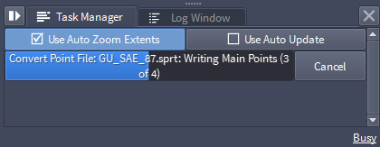
![[B]](../../_images/SQ_DOCS_BlueRectangle_163.png) You can stop the preview points loading at any time by pressing the [Cancel] button of the preview task in the Task Manager (located by default in the bottom right corner of the User Interface):
You can stop the preview points loading at any time by pressing the [Cancel] button of the preview task in the Task Manager (located by default in the bottom right corner of the User Interface):

- The green progress bar shows that the PointLoader001 object is part of the green Document.
- The text shows that it is building preview points.
Caching The Binary File To SPRT Format
- Having seen a preview of the point cloud, we can now cache the data to SEQUOIA’s own SPRT file format (assuming we like what we saw in the preview).
Press the [Build SPRT Cache] button in the Point Loader’s Input File rollout.
What will happen if I want to load the .E57 file again in a different document?
- If you would pick the .SPRT from the folder instead of the original .E57 source, the .SPRT will be loaded immediately.
- Assuming that both the original .E57 file and the .SPRT file are in the same folder, and you picked the .E57 file instead, the Point Loader will
- Display both the source File and the Cache paths;
- The Load SPRT Cache checkbutton will be checked automatically;
- The lowest Level Of Detail (LOD 0) will be loaded from the SPRT file.
- If you happen to load the same data into a different Document during the same SEQUOIA session, the loading might even be sped up by reusing the Data Cache which is shared between Documents!
Re-Caching The Binary File To SPRT Format
- Let’s assume that a customer has sent an updated version of the point data using a file with exactly the same name as the old E57.
- Attempting to load the new file will detect a discrepancy with the file info stored in the SPRT metadata (file size, file modified date etc.) and a warning will be displaying in the Status line.
- However, the existing SPRT cache can still be loaded, with the understanding that its data might not represent the content of the new source file.
- You can press the Build SPRT Cache button at any time to rebuild the SPRT cache and resolve the problem.
Meshing A Portion Of A Point Cloud
- Before actually meshing a very large point cloud that can take several minutes to process, we typically want to make sure our Mesher settings are adequate by testing out a small representative section of the whole dataset.
- SEQUOIA offers a dedicated Point Region Of Interest object (“ROI” for short) which can be connected to a Point Loader and filters out points that are outside or inside a specified box-shaped volume.
- Then, a Mesher object gets connected to the ROI object and only works on the filtered region.
Creating a Point ROI Object
Make sure the Point Loader is still selected in the Viewport - if necessary, click with the mouse on it in the Viewport to select it, or click on the object’s name in the Document Explorer.
Click the New Point Region Of Interest icon: 
- A new Point Region Of Interest object will be created in the Document and will be connected automatically to the selected Point Loader.
What if I don’t have the Point Loader selected when I make the Point Region Of Interest object?
- You can create a Point Region Of Interest without connecting it automatically, but then you will have to perform a few manual steps:
- In the Object Properties Panel on the right side of the SEQUOIA UI, click the [Add...] button found in the “Point Sources” rollout of the Point ROI object - a Point Sources dialog with a list of valid point sources will open.
- Double-click the Point Loader on the Point Sources list, or single-click it and then press the [OK] button.
- Now that the two objects are connected, press the [Fit Points] button found in the Region Box Settings rollout - this will set the size of the Point ROI’s Gizmo to the bounding box of the dataset.
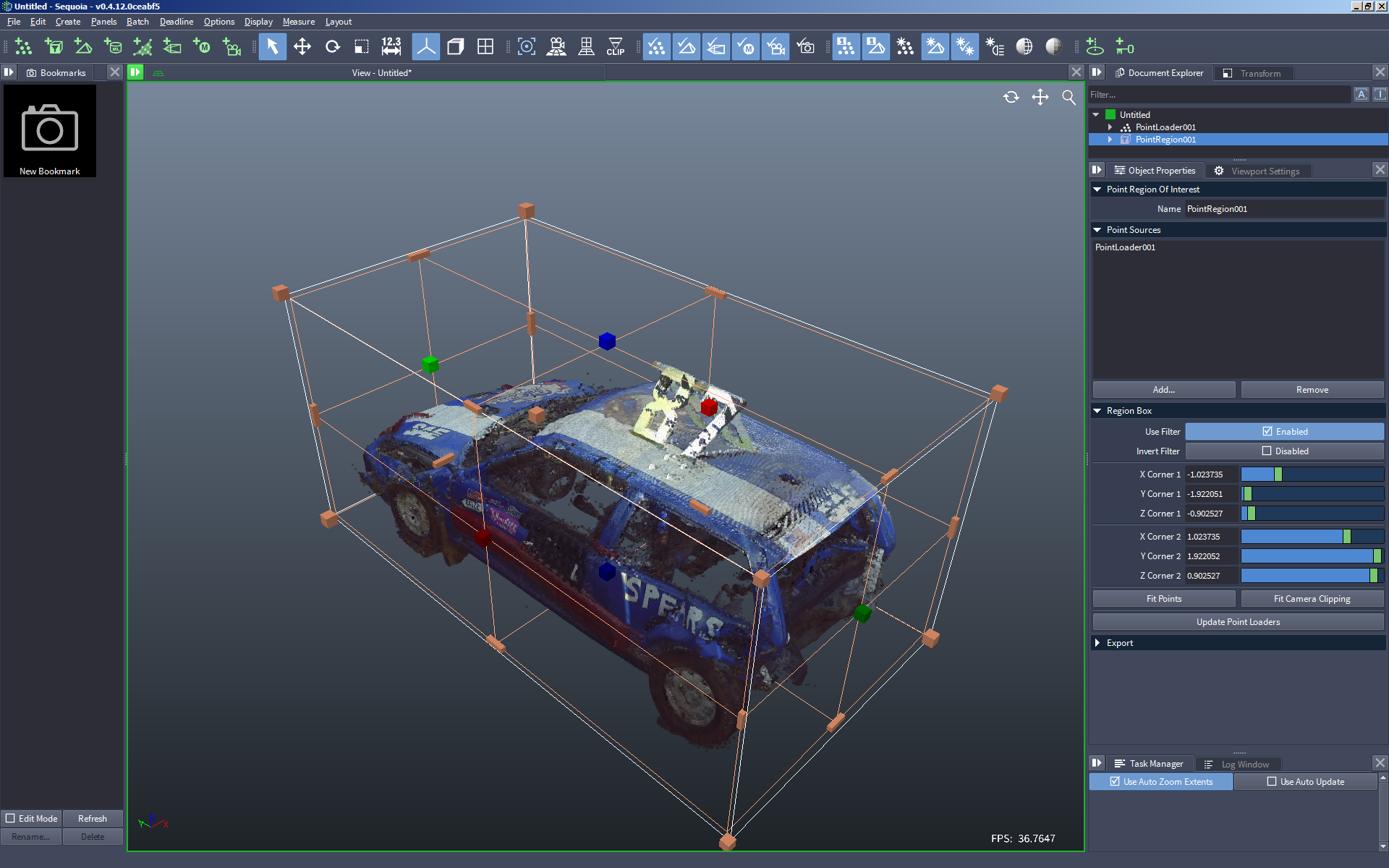
Adjusting The Point ROI Region Box
- The Point ROI object displays a very prominent Region Box “gizmo” in the viewport - you can grab the box-shaped handles and drag them to resize the Region to enclose only a fraction of the whole Point Cloud.
- Alternatively, you can enter the XYZ coordinates of the Minimum and Maximum corners of the Region Box directly in the Object Properties Pabel of the Point ROI.
- Clicking and holding the Left Mouse Button pressed while dragging the mouse over the red boxes will resize the Region Box along its X axis - the bright red box represents the Positive X, the darker red is the Negative X axis.
- The Green and Blue boxes represent the Y and Z axes, respectively.
- Holding down the CTRL key while dragging one of these handles will scale both sides symmetrically, adjusting the positive and negative axes at the same time.
- Dragging the elongated yellow handles at the edges of the Region Box will adjust two axes at once relative to the edge along the diagonal of the Region Box.
- Holding down the CTRL key while dragging one of these edge handles will adjust both axes symmetrically relatve to the center of the Region Box.
- Dragging the yellow corner box-shaped handles will adjust all 3 axes at once relatively to the corner that is on the opposite side of the Region Box.
- Holding down the CTRL key while dragging one of these corner handles will adjust all three axes symmetrically relatve to the center of the Region Box.
- If the data source is aligned well along the world axes, it can be very convenient to adjust one or two axes at a time in an orthogonal view (Front, Top, Left etc.)
- Press the T key to switch to Top view, then drag the handles to adjust the size of the Region Box as seen from above.
- Press the F key to look at the Point Cloud from the Front, then drag the handles to adjust another axis.
- Press the R key to look at the Point Cloud from the Right, then drag the handles to adjust yet another axis, and so on until you are happy with the dimensions of the Region Box.
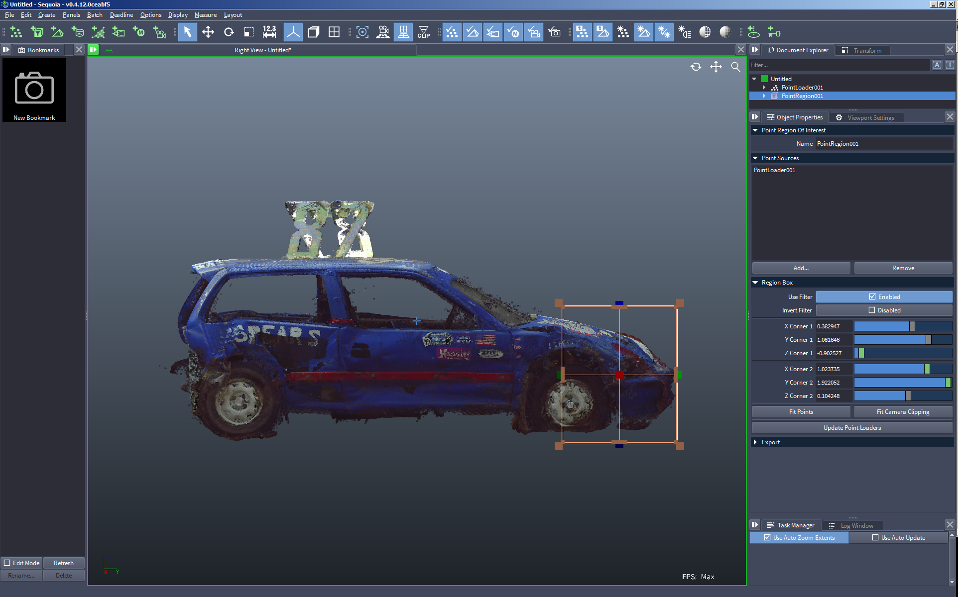
Creating And Connecting A Mesher Object
- The actual Mesh generation from the filtered Point Cloud is performed by the dedicated Mesher object.
Make sure the Point ROI object is still selected - if it is not, reselect it by clicking on its name in the Document Explorer, or by clicking on its Region Box in the viewport.
Click the New Mesher icon: 
- A new Mesher will be created and will be automaticlaly connected to the previously selected Point Region Of Interest object.
The Suggested Radius Value
- The SEQUOIA Meshing approach involves the creation of a two-sided mesh passing around the Point Data.
- The Radius value of the Mesher represents the average distance between neighboring points.
- If the Radius value is too small, the individual points will not “merge” and can produce separate unconnected spherical “blobs”.
- If the Radius value is too large, the resulting mesh will be very thick and won’t represent the details of the original geometry very well.
- To help with the selection of an appropriate value, SEQUOIA’s Mesher object offers a Suggested Radius feature.
- When the Mesher is created and connected to the point source (in our case, a Point ROI filtering a Point Loader), the Mesher will read through the particle data and propose a plausible value.
- Note that this value might be close to the optimal one, but it is up to the user to determine which Radius works best for a specific data set, balancing quality and meshing performance.
- If more point sources are added later, you can recalculate the Suggested Radius value by clicking the [Suggest Radius] button.
- To set the Radius value to the suggestion, simply click the [Set Radius to ....] button.
- The [Set Radius to XXX] button will be updated continuously while the Mesher scans through the point data.
- With very large point clouds, reading through the whole data can take minutes, but you can watch the suggested value and if it stops changing significantly, you can click the button to set the Radius at any time.
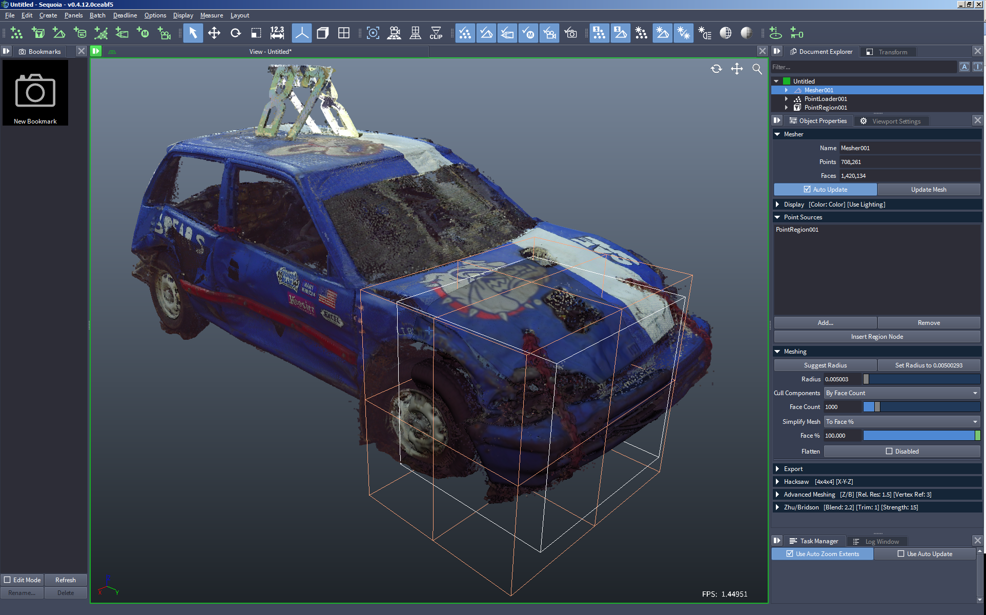
Meshing The Filtered Points
- In most cases, the default settings of the Mesher will work well for a first iteration.
- After the first meshing iteration, you can always adjust the Radius to a higher or lower value to tweak the results.
Press the [Update Mesh] button - a Meshing Task will be scheduled in the Task Manager:
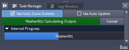
- The meshing could take from a few seconds to a few minutes depending on the number of points in the source, the size of the Point Region Of Interest, and the hardware used.
- The following example took about 7 seconds:
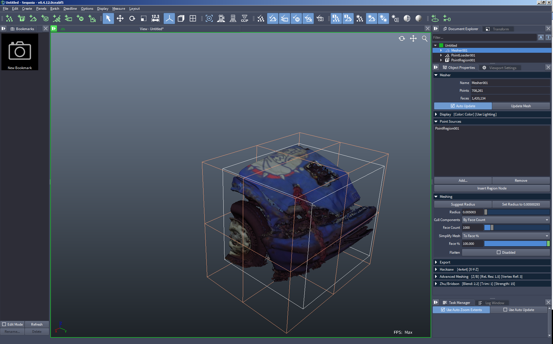
- You can disable the points display in the Viewport to see only the mesh.
Click the Toggle POINTS Display In The Current Viewport icon ![]() to turn Point Display off:
to turn Point Display off:
Reducing The Mesh
- The resulting mesh output is usually very dense and the vertex count is quite comparable to the Point Cloud count.
- You can use the Simplify controls in the Mesher object to reduce the density by specifying either a Percentage or a Target Face Count.
- The Mesher already defaults to “By Face %”, but the actual Percentage defaults to 100% to produce the full output.
Change the “Face %” value to 10%
Click the [Update Mesh] button.
![[R]](../../_images/SQ_DOCS_RedCircle_164.png) Note that the actual meshing process will not be repeated.
Note that the actual meshing process will not be repeated.
- The resulting full mesh has been cached by SEQUOIA in memory, and only the actual optimization will be performed on top of the existing data!
Change the “Face %” value to 1.0 and click the [Update Mesh] button again
- The original 100% mesh will be optimized again to produce an even lower polygon count.
Switch the “Face %” back to 10.0 and press [Update Mesh]
- The result will be loaded from the Cache immediately!
Meshing The Whole Point Cloud
- Once you have confirmed that the current meshing settings including “Radius” and “Face %” work well with the source data, you could request the whole mesh to be generated.
Select the Point ROI object and turn it off by unchecking the “Use Filter: Enabled” checkbutton
- This will pass all point data through the Point ROI without filtering it.
Note: it is also possible to press the [Fit Points] button in the Point ROI, or delete the Point ROI completely, but these options are not recommended over the Pass Through method described above.
How About Larger Datasets?
- However, some point clouds can contain billions of points.
- It is unrealistic to expect SEQUOIA to mesh such data on an average machine due to memory limitations.
- The Hacksaw feature of the SEQUOIA Mesher solves this problem.