Single Sided Meshing Using Scanner Position
Overview
- In the following tutorial, we will create a single sided mesh from an architectural scan containing Scanner Position metadata.
- We will use a .PTG file provided by FARO for the Autodesk REAL conference in 2015.
Loading The PTG File And Its SPRT Cache
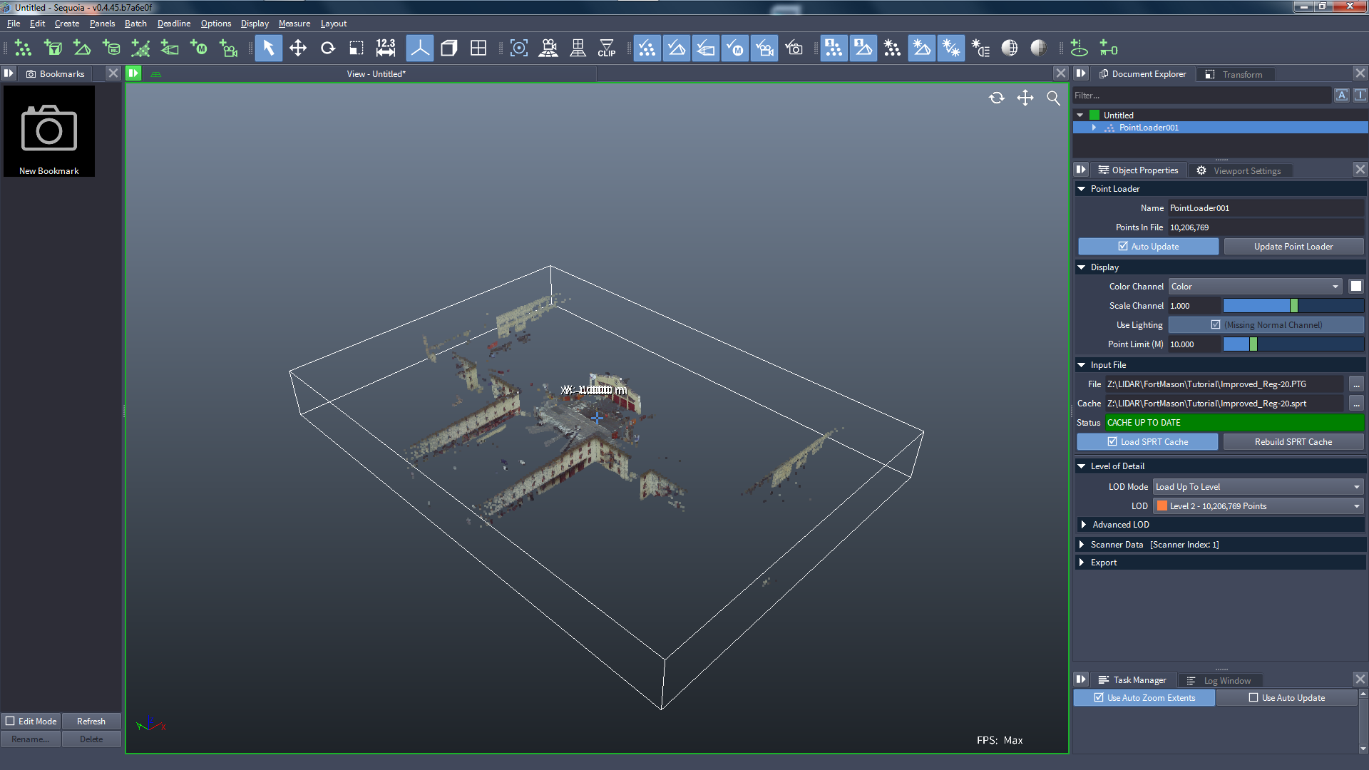
![[G]](../../_images/SQ_DOCS_GreenArrow_161.png) Create a Point Loader and pick the PTG file.
Create a Point Loader and pick the PTG file.
- If there is already a matching SPRT cache in the same folder, it will be loaded.
- Otherwise, press the Build SPRT Cache button.
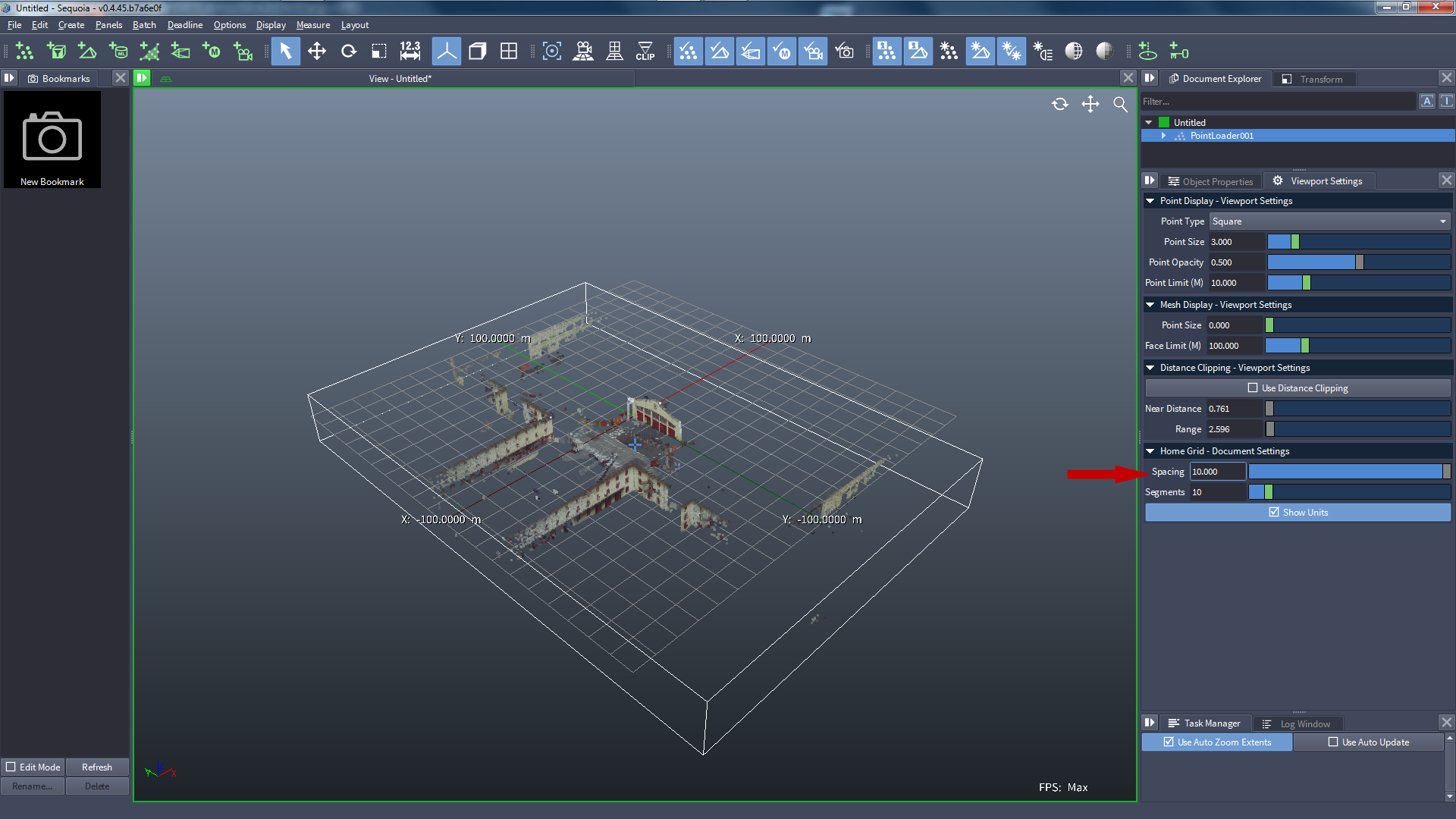
Switch to the Viewport Settings tab next to the Object Properties panel, and change the Spacing to 10.0 meters.
Defining A Point Region Of Interest
With the Point Loader still selected, create a Point Region Of Interest object.
- It will be connected automatically to the Point Loader.
- Its gizmo will be fitted to the bounding box of the point data.
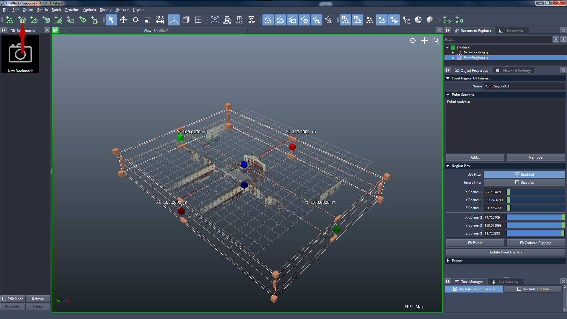
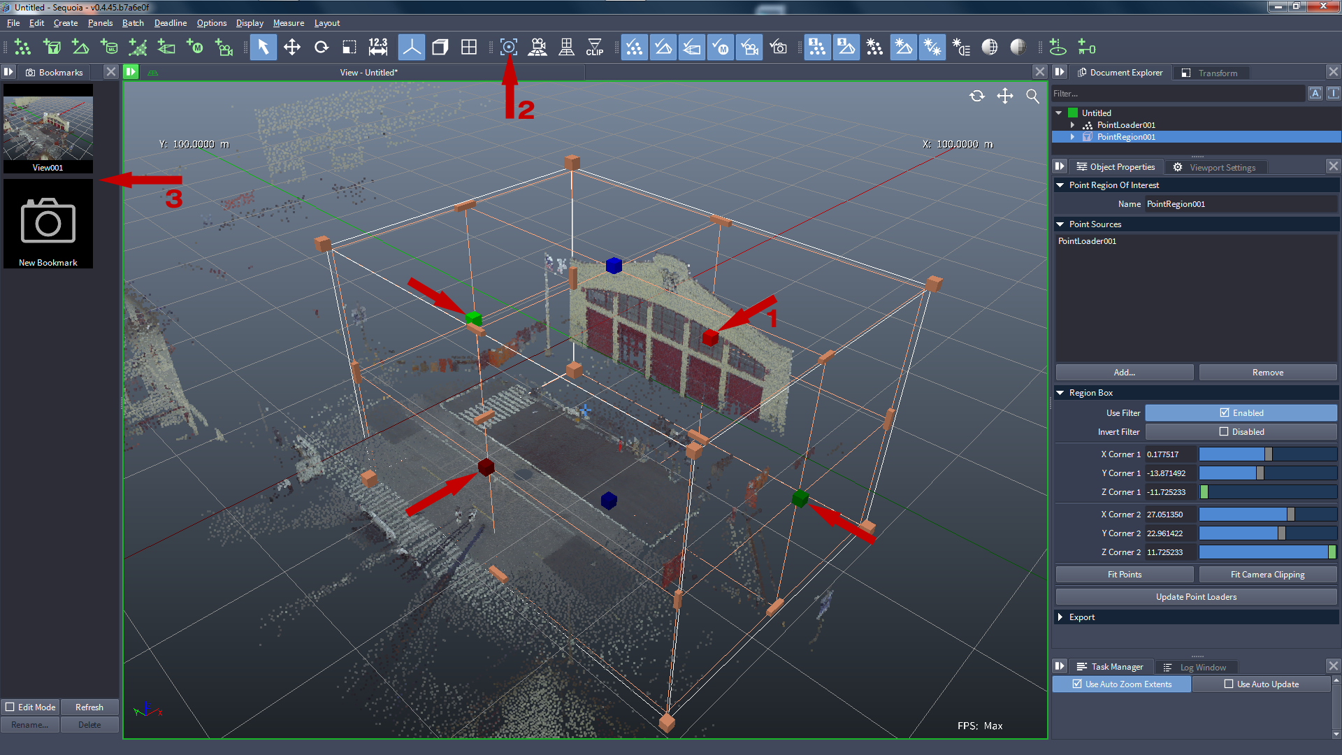
Adjust the Point Region Of Interest gizmo to enclose only the entrance of the building.
Press Z or press the Zoom Extents icon [2] to zoom at the Point Region Of Interest gizmo.
Press the New Bookmark icon [3] to store the current view.
Meshing The Points
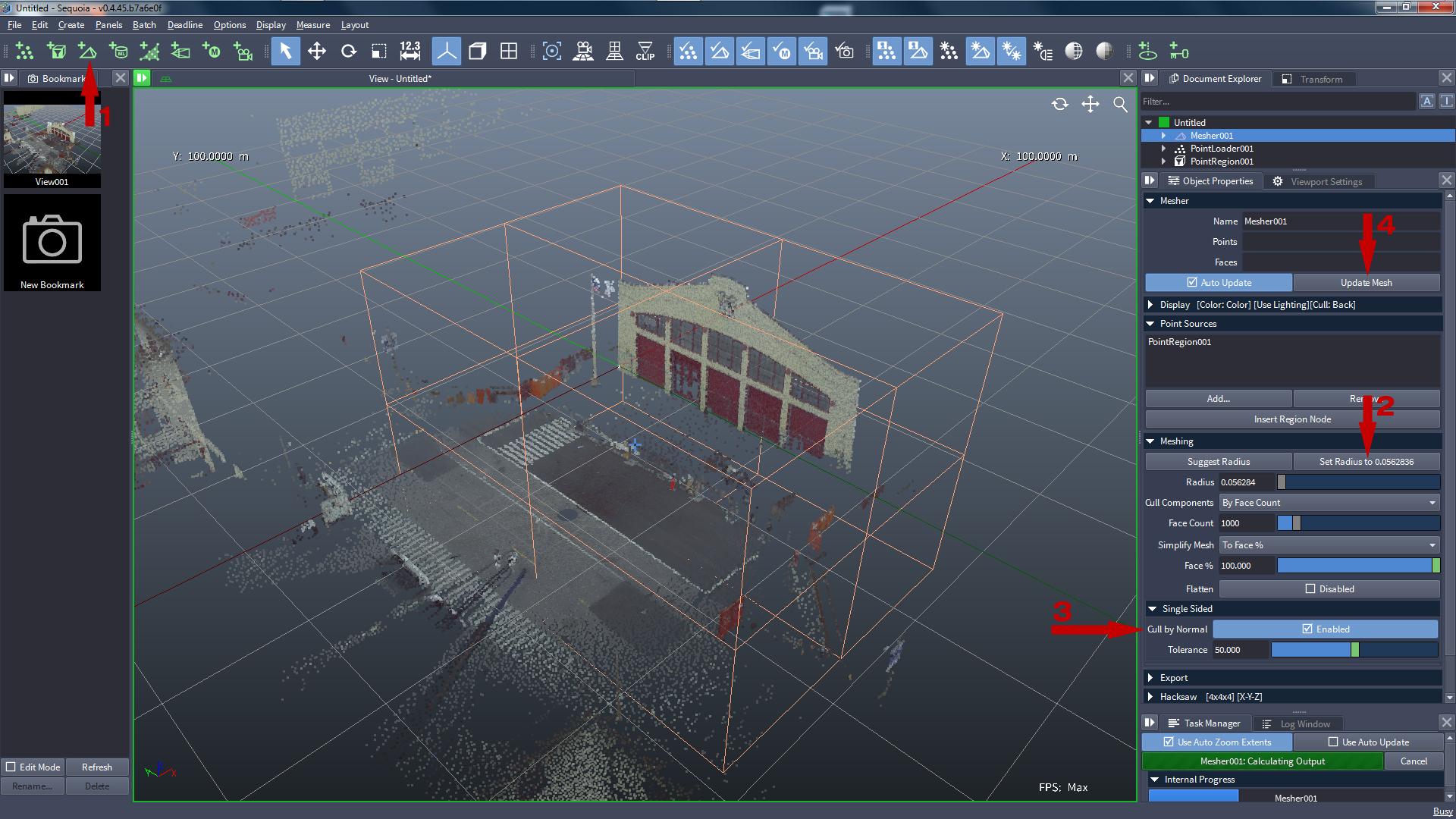
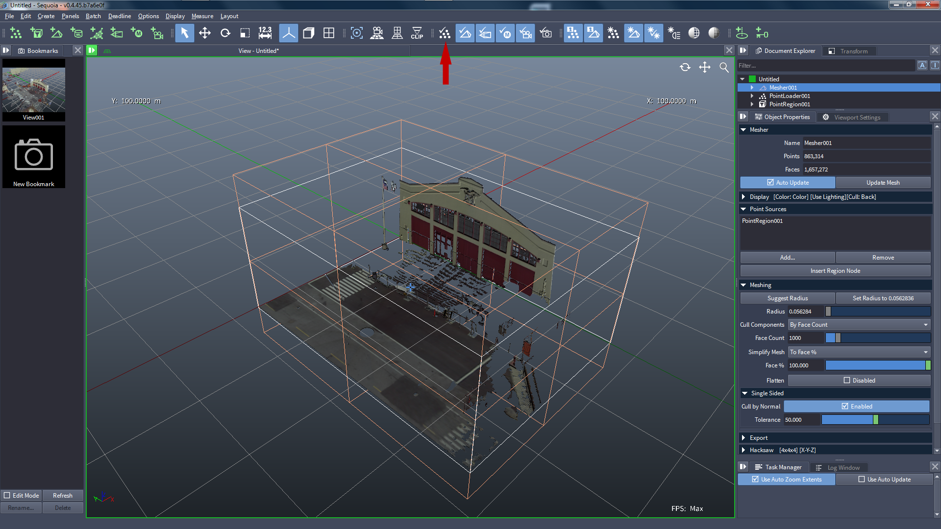
With the Point Region Of Interest still selected, create a Mesher object [1].
Press the Set Radius to .... button to accept the suggested Radius value [2].
Enable the option Cull by Normals [3] - this is premature, but let’s see what will happen!
Press the Update Mesh button [4] (or hit F5).
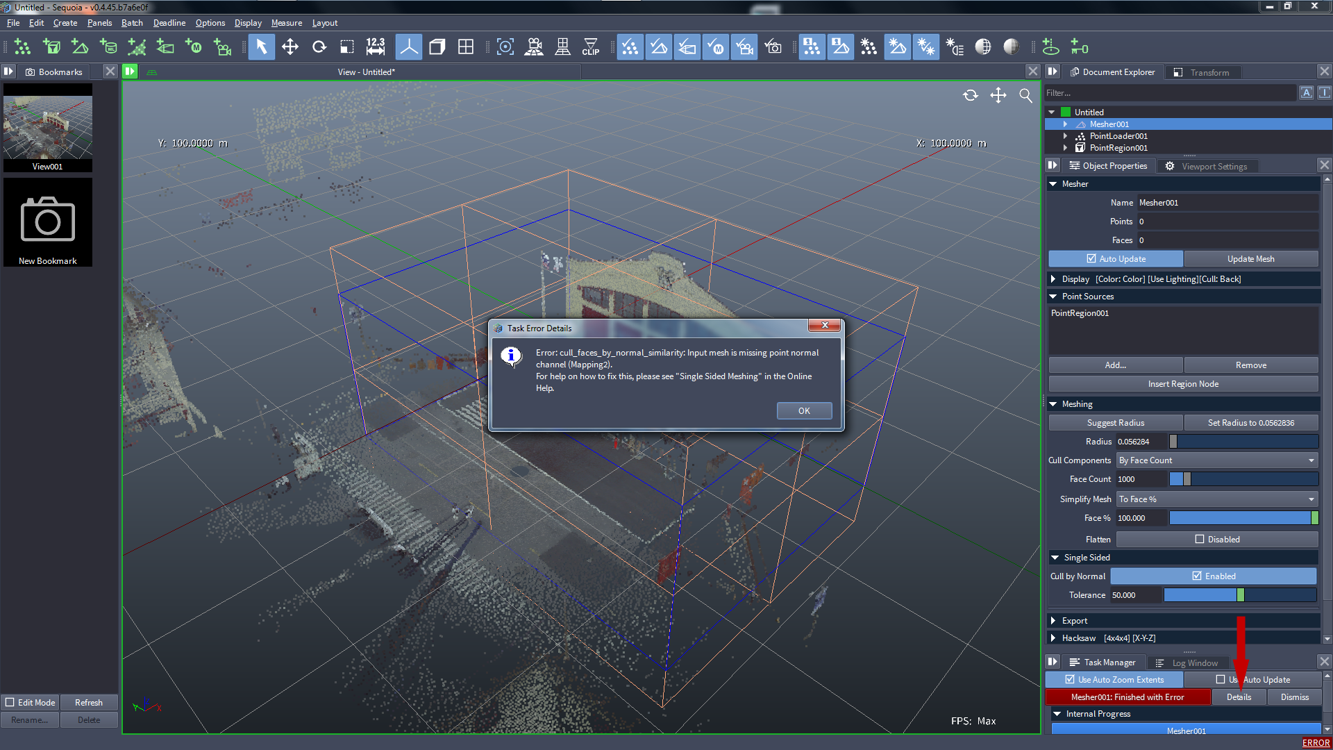
![[R]](../../_images/SQ_DOCS_RedCircle_164.png) Since we have not provided a valid Normal channel in the Point Loader, the Meshing will finish with an ERROR:
Since we have not provided a valid Normal channel in the Point Loader, the Meshing will finish with an ERROR:
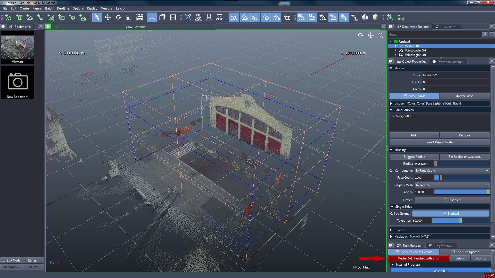
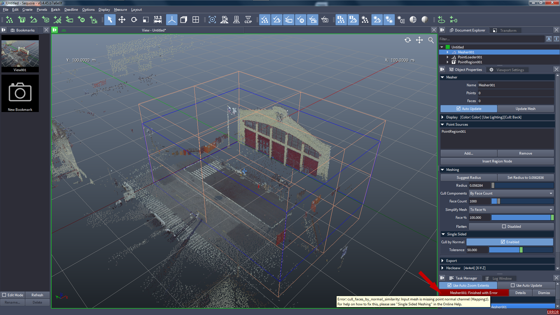
To see the actual error message, place the mouse pointer over the progress bar and look for the tooltip:
Alternatively, press the Details button to show an error popup.
Once you understand the error, press the Dismiss button to remove the entry from the Task Manager.
![[B]](../../_images/SQ_DOCS_BlueRectangle_163.png) Clicking the ERROR link at the bottom right corner will remove it and switch to the Log tab where you can look through the reports and find the actual error message.
Clicking the ERROR link at the bottom right corner will remove it and switch to the Log tab where you can look through the reports and find the actual error message.
Generating Normal Channel From Scanner Position
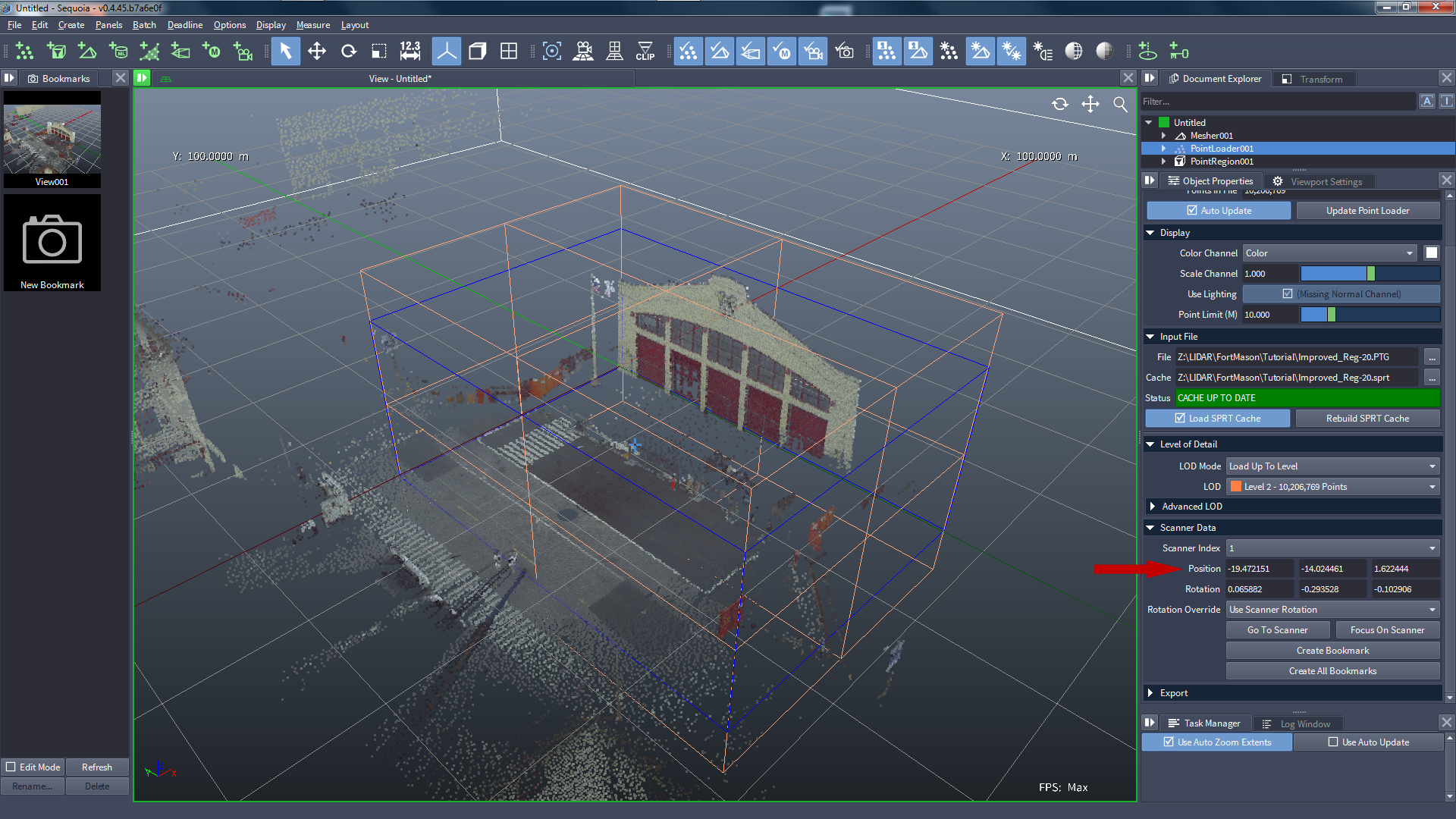
Select the Point Loader and expand the Scanner Data rollout.
- There is a valid Scanner Index 1 representing the position where the scanner was located when the point data was generated.
- Let’s use this position to generate a “visibility vector” from the point to the scanner and store it in the Normal channel.
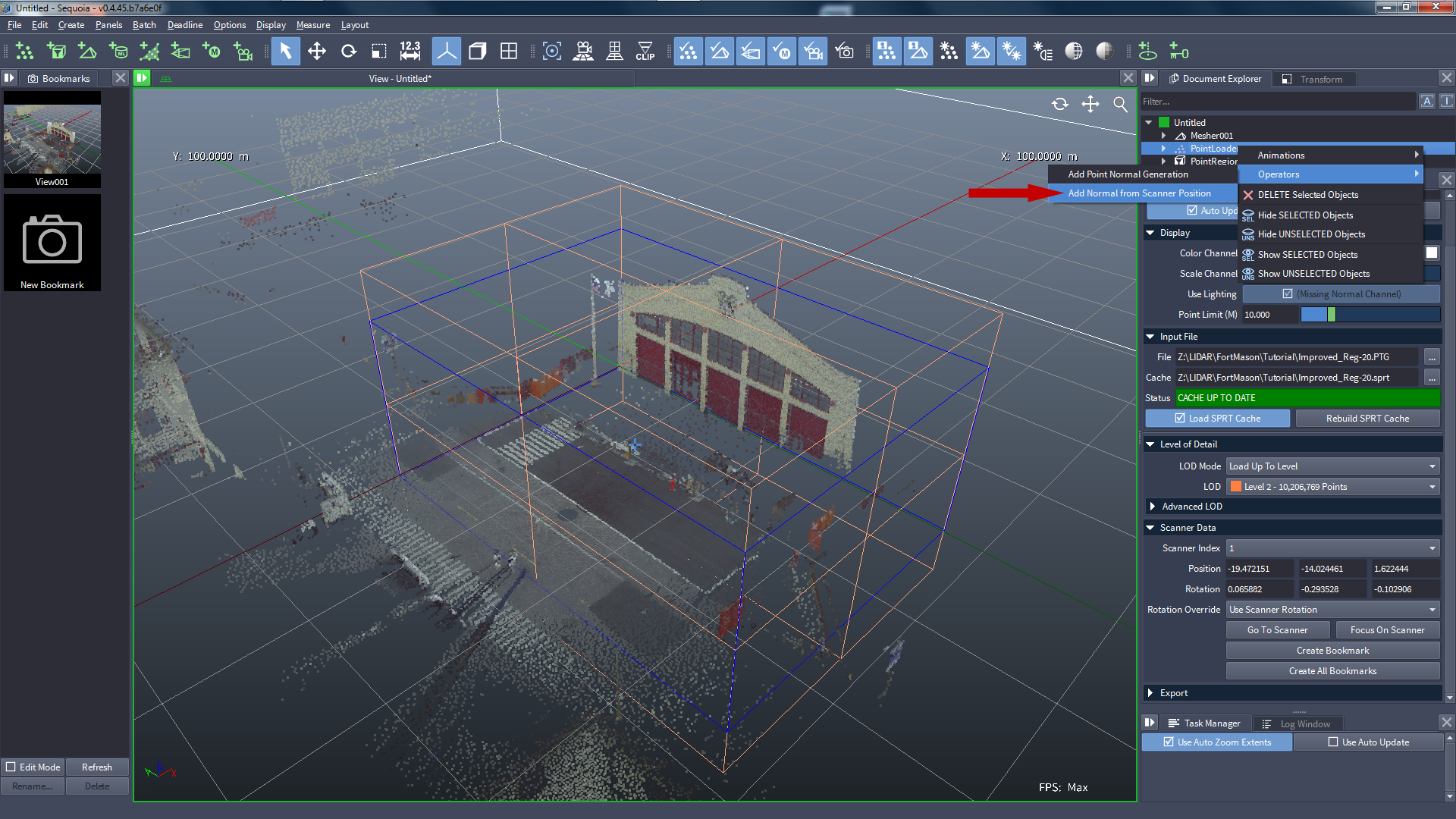
Right-click the Point Loader and select Operators > Add Normal from Scanner Position:
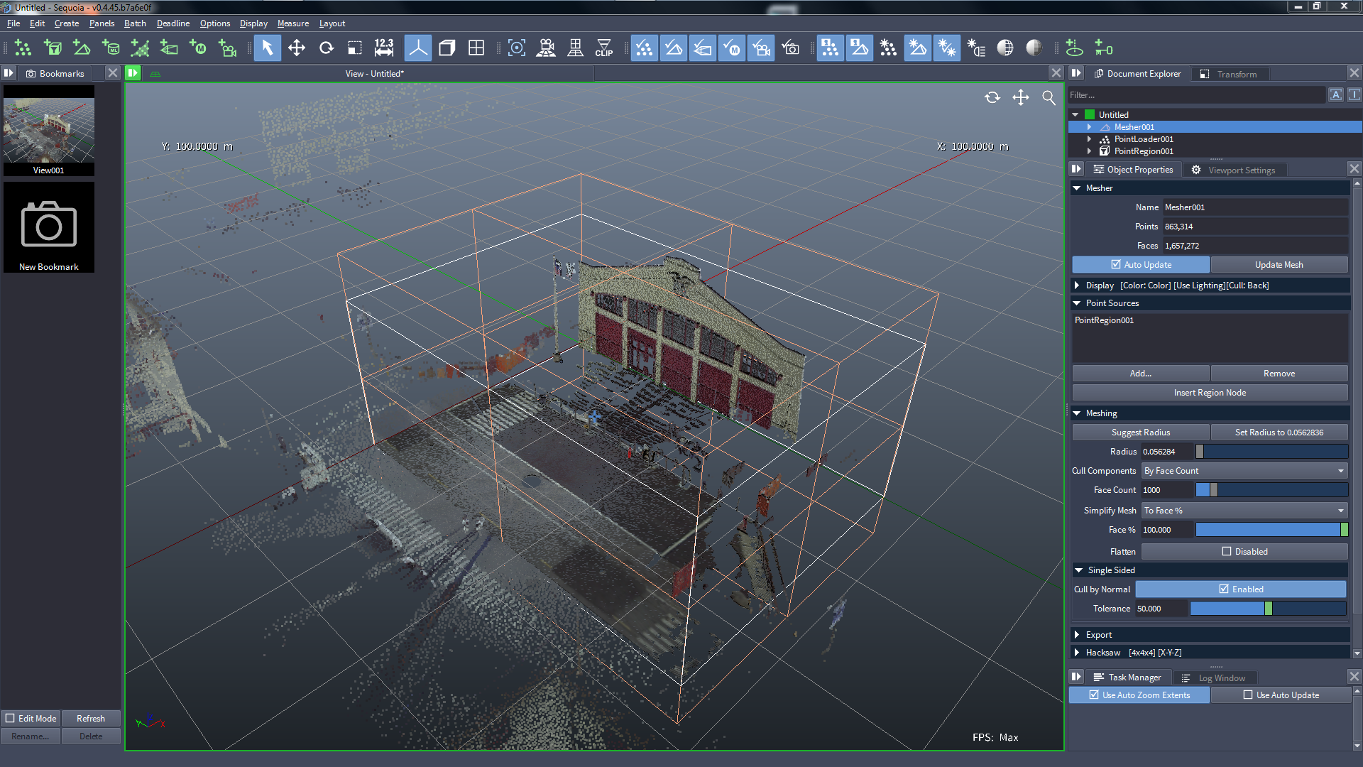
Select the Mesher and press the Update Mesh button (or hit F5)
- Once the meshing is finished, a valid mesh will appear in the Viewport.
Uncheck the Display Points icon to show only the mesh:
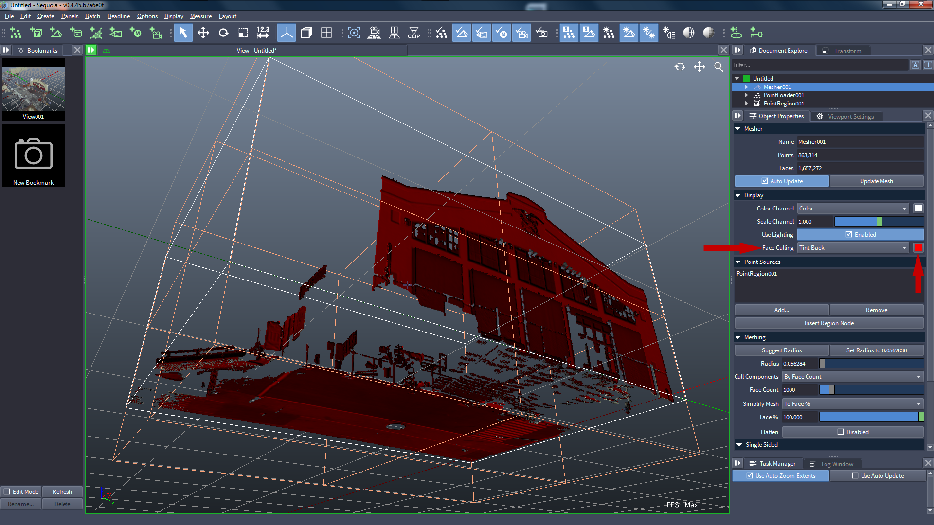
Switch the Display rollout > Face Culling to Tint Back and adjust the color to pure red.
- The backside of the single-sided mesh will be tinted red:
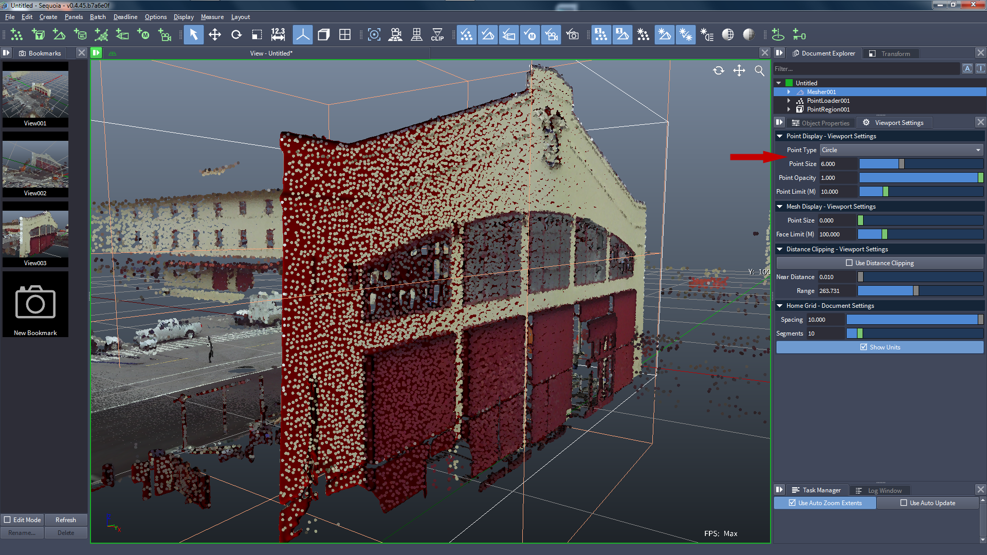
Check the Display Points icon again.
Switch the Viewport Settings > Point Type to Circle
Change Point Size to 6.0 to see larger circles.
- The mesh is obviously passing on the one side of the points and does not intersect them.
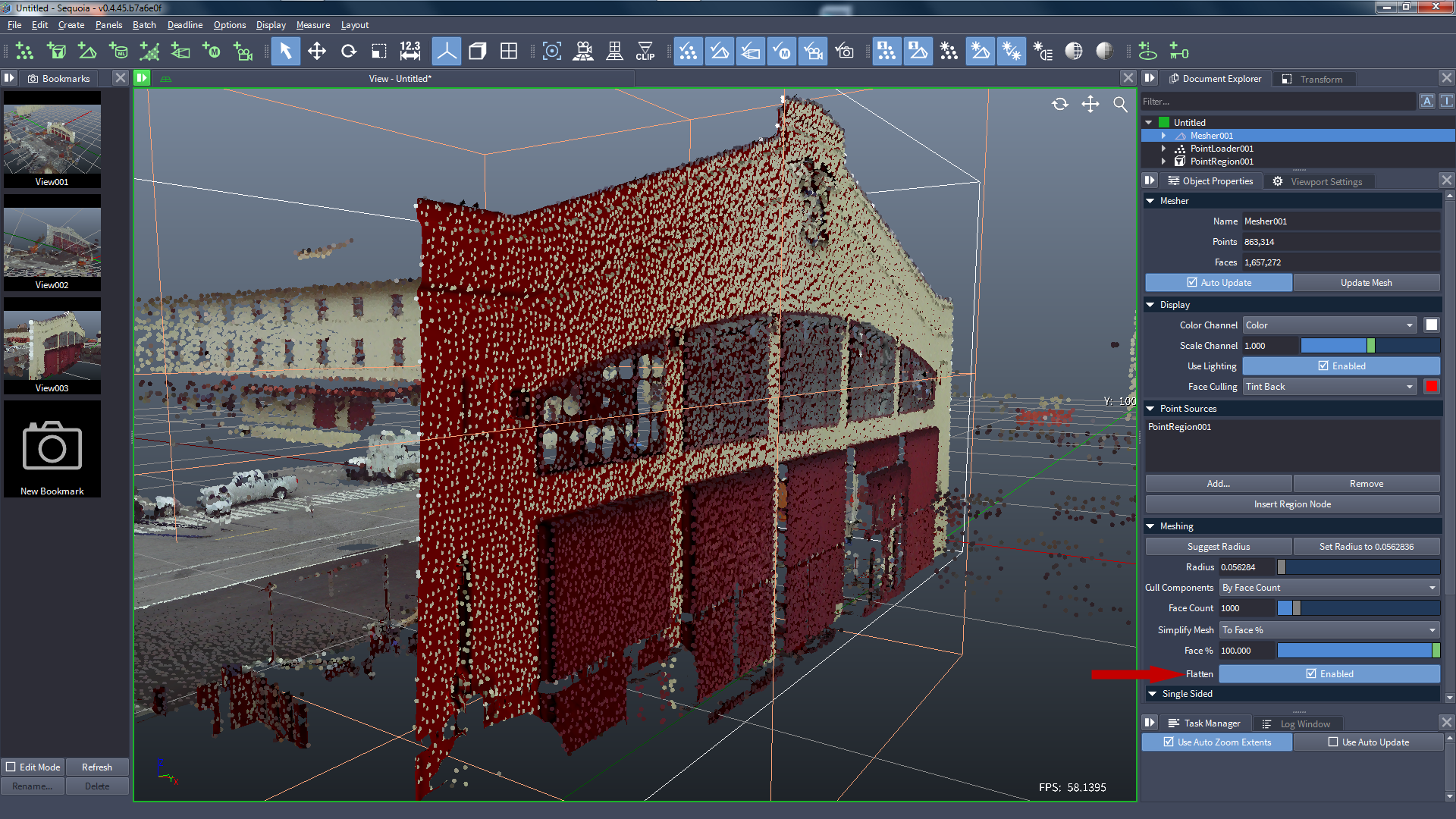
In the Object Properties panel, check the Flatten option of the Mesher, then hit F5.
- The mesh will be pushed towards the point cloud, and will intersect with the points, resulting in mostly semi-circles:
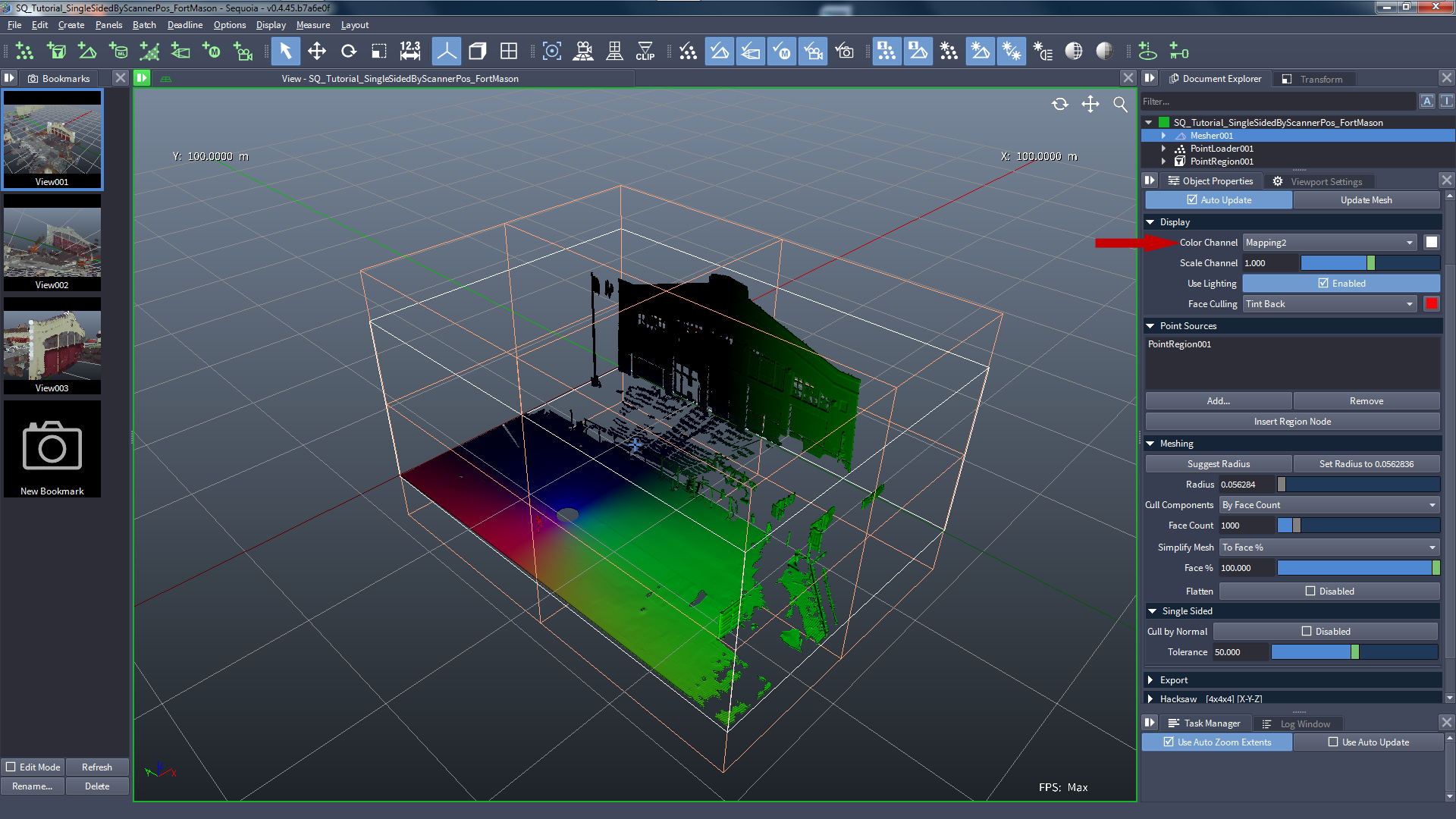
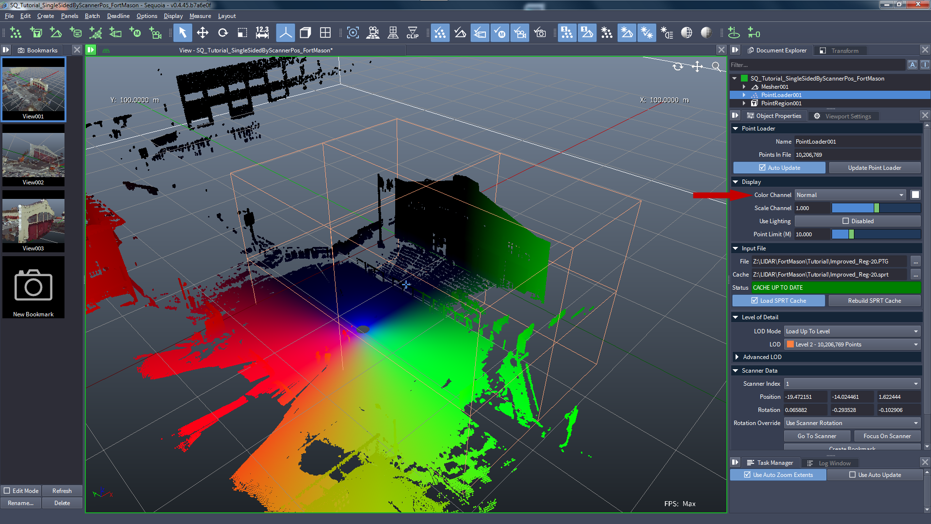
What does the Normal From Scanner Position data look like?
- The Normal channel generated by the operator can be visualized as Color in the Viewport:
- The Mapping2 channel of the Mesher is the content of the same channel, encoded into the Mesh: