Point Loader Object
Overview
The Point Loader object is responsible for the reading of point data from a specified data file on disk.
The Point Loader loads the data in object space and can transform the point cloud into world space according to its Transformation values.
You can learn more about Point Loader related workflows here.
The Point Loader exposes the following UI Controls in the Object Properties panel:
Point Loader Rollout
The Point Loader rollout displays the name of the object and the total point count on disk.
It also contains the Auto Update option and the button to trigger the Update of the point data.
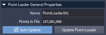
Name Field
The Name field shows the name of the selected Point Loader.
The name is generated automatically in the form PointLoaderNNN, where NNN is an integer padded to 3 digits, starting and 1 and incremented with each new Point Loader creation.
The name can be edited by the user to better describe the purpose/function of the object.
Points In File Field
The Points In File field shows the number of points in the source file.
The field is Read-only - you can select and copy the value, but cannot change it.
Auto Update Checkbutton
When unchecked, the reloading of the point data can be triggered only manually by pressing the [Update Point Loader] button (see below).
When checked (default), the point data will be reloaded automatically after every change to the Point Loader’s properties, as long as the [Use Auto Update] global option in the Task Manager is also checked.
If a previous update task is already queued in the Task Manager, it will be replaced by the new task.
By default, the update will start 1 second (1000 ms) after the last change. This value can be modified using Options > Configuration > Auto Update Delay (milliseconds).
Update Point Loader Button
Pressing this button will force the loading of the specified point file using the current settings.
When pressed, a new Task will be added to the Task Manager and the loading will be performed asynchronously in the background without blocking the UI and Viewports.
Note that selecting the Point Loader and pressing F5 or picking the Main Menu > Display > Update Selected Object menu item will have a similar effect, but will also update any dependent objects (for example Point Region Of Interest and Mesher) in addition to reloading the points.
Display Rollout
The Display Rollout contains the controls over the viewport display of the points.
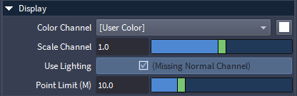
Color Channel Dropdown List
The Color Channels list defines the data source to be used to draw the points in the Viewport.
The Color Channel list contains the point data channels found in the file, plus a [User Color] entry which enables the override color swatch to the right.
When the point data file contains a valid Color channel, the list will default to it.
The list typically contains one of the following color sources:
[User Color] - overrides the color of all points with the User Color value defined by the swatch next to the list
Color - uses the Color channel (either native, or converted by mapping other channels during source file conversion).
Intensity - uses the Intensity channel which is an single Floating point value typically representing the intensity of the return signal of the laser beam.
Position - all point data files contain at least a Position channel defining the 3D positions of the samples.
Normal - an optional channel usually generated by 3D tools like Krakatoa defining an orientation of the point that allows surface-like shading.
Note that switching to any of the optional Channels like Intensity, Position and Normal requires the reloading of the data from disk by pressing the [Update Point Loader] button for the change to take effect.
Switching to [User Color] override does not require a reloading of the point data.
User Color Swatch
Defaults to White.
Defines a single override color to be assigned to all points when displaying in the Viewports.
Clicking on the swatch to open the Color Picker will also automatically switch the Color Channel list to [User Color] for the change to take immediate effect.
Scale Channel Slider
Scales the Color Channel values.
Defaults to 1.0.
Use Lighting Checkbutton
Only enabled when a Normal channel is found in the point data.
When disabled, it will list the reason (Missing Normal Channel) in its caption.
When enabled, it can be checked to allow the shading of the points using the scene lights (if enabled for the Viewport via the Viewport Lighting And Shading toolbar).
When unchecked, no lighting will be performed.
Point Limit (M) Slider
Defines an object-specific display point count limit.
Default is 10 million.
The Point Loader will only show up to this number of points in the Viewports.
This value does not affect export and meshing.
Note that the Viewport Settings panel provides a higher-priority viewport-specific Point Limit which could be lower than the object’s own limit.
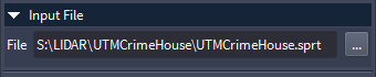
Input File Rollout
The Input File rollout will change its appearance depending on the type of input file.
When the source file is a SEQIOIA native .SPRT file previously converted from another source, only one File control will appear to represent the source file name.
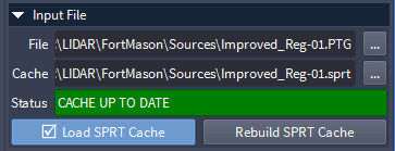
When the source file is any other file format but .SPRT, additional controls for the conversion and caching to SPRT will be displayed in the Input File Rollout, and an additional Load SPRT Cache checkbutton will appear.
If no SPRT Cache file with the same name and path as the source file can be found, the Status line will read “MISSING CACHE FILE” on red background, and the Load SPRT Cache option will be unchecked.

If the expected SPRT Cache file exists and its metadata matches the source file, the Status line will read “CACHE UP TO DATE” on green background, and the Load SPRT Cache option will be checked automatically.
If the SPRT Cache file exists, but is an older 1.0 version created during the early beta of SEQUOIA, the Status line will read OBSOLETE SPRT1 CACHE FILE on dark orange background.
The SPRT1 file will still be loaded, but some advanced features might not behave as well as with the latest SPRT v2 Cache files.
You can press the Rebuild SPRT Cache button to update the file.

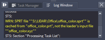
If the SPRT Cache file exists and is the correct version, but its metadata describing the source file it was created from does not match the current source, the Status line will read “CACHE METADATA MISTMATCH (See Log)”

The Log Panel of SEQUOIA will list a Warning explaining the cause for the message:
File Filename Field And Button
Contains the path and filename of the point cloud data file to load.
The name can not be entered manually - it must be picked through a file browser dialog by clicking the […] button on the right.
When the Point Loader is first created, the file browser dialog will pop up automatically at the last known folder location, saving you the click on the […] button.
Cache Filename Field And Button
Contains the path and filename of the Cache data file.
The Cache data filename is set automatically to the same filename as the source File, but with a native SEQUOIA extension.
NOTE on SPRT vs TEST_SPRT: In the current Beta builds, the Cache will be set to .test_sprt which is a Work In Progress implementation of the Thinkbox Spatial PRT format Version 2. It is expected to be the main and only format supported by the release version of SEQUOIA 1.0
Status Line
The Status line displays information about the status of the Cache file listed in the Cache.
The background color of the Status line will change between GREEN, ORANGE and RED depending on the Cache status.
Please see earlier on this page for descriptions and screenshots.
Load SPRT Cache Checkbutton
Checked automatically when a matching SPRT file is found next to the non-SPRT source file.
When checked, the SPRT cache will be loaded instead of the original source file.
Unchecking the checkbutton will cause the original non-SPRT file to be read and previewed in the viewport.
Build / Rebuild SPRT Cache
When there is no matching SPRT cache file for the current source file, the button will read Build SPRT Cache.
When there is a matching SPRT cache file for the current source file, the button will read Rebuild SPRT Cache.
Pressing this button will read the source file and build a new SPRT cache file from it.
This will replace any existing SPRT cache file with the same name, and update its metadata to reference the source it was made from.
Run Precision Analysis and Build SPRT Cache
Pressing this button will both perform precision analysis and build the SPRT file.
Precision Information Rollout
This rollout is collapsed automatically when an SPRT Cache exists and Load SPRT Cache is checked, and expanded otherwise.
This controls contained in this rollout can be used to analyze the source file precision and determine the optimal SPRT storage method to preserve the source data’s precision.
Run Precision Analyses
Minimum and Maximum Values
These values represent the minimum and maximum extents of the source data’s bounding box relative to the data’s origin.
The Min row of values shows the X, Y and Z values of the data bounding box’s minumum in real-world units adjusted to the magnitude of the data (meters, kilometers. centimeters etc.)
The Max row of values shows the X, Y and Z values of the data bounding box’s maximum.
Magnitude / Spreead Values
These values represent the Magnitude and Spread of the data.
The Magnitude represents the largest position component of a point data value, and this signifies the largest value that will beed to be represented at the desired precision.
The Spread represents the largest difference between the minimum and maximum components.
Both values are represented in real-world units which adapt to the magnitudes of the values.
Desired Precision Slider
This value defines the desired precision to be retained by the SPRT cache file after converting the source point cloud file.
It defaults to 0.1mm which is lower than the typical resolution of LIDAR scanners.
The value can be changed by the user to match other hardware or project requirements.
This value informs the automatic SPRT Mode suggestion based on the Magnitude and Spread of the input data.
SPRT Mode Dropdown List
This control will be disabled by default, it can be enabled for manual access by unchecking the**Automatic** option next to it.
This list offers access to the storage modes supported by the SPRT file format:
Single - position data will be stored using 32 bit floating point numbers relative to the world origin.
Single+Offset - position data will be stored using 32 bit floating point numbers expressed relatively to the voxel origin, which on itself will be stored as a 64 bit Double.
Double - position data will be stored using 64 bit floating point numbers relative to the world origin.
Automatic Checkbutton
When checked (default), the SPRT Mode (see above) will be determined automatically based on the source data’s Magnitude, Spread, and the Desired Precision value set by the user.
When unchecked, the SPRT Moder can be set manually by the user even if it is not the optimal
Status Field
This text field offers feedback about the SPRT Mode selected automatically or manually.
Green background denotes positive outcome.
Orange background denotes a warning of possible loss of precision.
Details… Button
Pressing this button opens the Precision Information dialog
It offers insight into the Automatic or Manual precision selection and related warnings.
Import Preview Display Rollout
The additional Import Display rollout controls the viewport preview of the source file before its conversion to a cache file.
This rollout can be hidden by unchecking the Import Display Mode checkbutton in the Input File rollout.

Load Mode Drop-down List
Specifies the mode for loading fractions of the file.
When set to “Load Every Nth Point” (default), requesting less than 100% to be loaded via the “Load Percentage” value will result in loading a fraction by skipping particles.
When set to “Load First N Points”, requesting less than 100% will load from the beginning of the file until the requested percentage has been reached.
When set to “Load Every Nth By ID”, requesting less than 100% will skip points, but if there is a valid ID channel in the file, points will be loaded based on their ID. If a second file with different positions is loaded, points with the same IDs will be loaded.
Use Point Limit Checkbutton
When unchecked (default), the point count requested via the “Load Percentage” value will be loaded.
When checked, an additional value control will appear, allowing you to specify a maximum number of points (in thousands) to load.
Point Limit x1000 Value Field
Visible only when “Use Point Limit” is checked.
Default value is 1000 (equivalent to 1 million points).
Defines a cap to the number of points to be loaded, overriding the file’s count and Load Percentage values.
This is useful if you know that you want to see only a specific number of points at once (for performance or other reasons), but you don’t know the exact number in the file yet or what the current settings would produce. Enabling and setting the limit will give you exactly the requested amount by stopping the loading once the count is reached.
Load Percentage Value Field And Slider
Default is 100.0, Minimum is 0.0, Maximum is 100.0.
When set to less than 100%, only the specified fraction of points will be loaded according to the previously described settings.
Level Of Detail Rollout
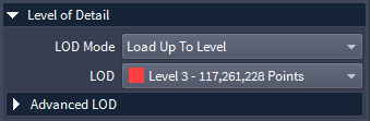
LOD Mode Dropdown List
Switches between a view-dependent adaptive Level Of Detail and a fixed Level Of Detail mode.
Possible values are:
Load Up To Level (default) - loads points in view-dependent manner from voxels up to the level specified by the LOD Dropdown list (see below).
Load Fixed Level - forces the display to a single LOD Level, ignoring lower and higher LOD Levels.
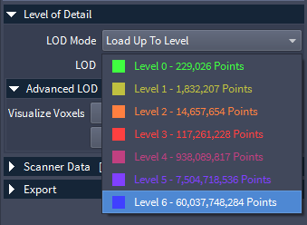
LOD Dropdown List
Lists all the LOD Levels available in the SPRT cache file.
Each entry is color-coded using a pre-defined gradient which is also used to visualize the Voxels of each level in the viewport.
Each entry contains the LOD number and the number of points in that particular Level.
By default, the Level 1 will be selected on the list, forcing the lowest Level Of Detail to be loaded for new Point Loaders.
Advanced LOD Rollout
This rollout is a child of the Level Of Detail rollout and is collapsed by default.
It contains mostly debugging controls, but it can be used by anyone to better understand and visualize the content of SPRT files.
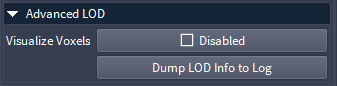
Visualize Voxels Checkbox
When checked, the currently loaded voxels will be drawn as wireframe boxes in the Viewport.
The voxels will be drawn in the color of their respective Level Of Detail (as seen in the LOD dropdown list).
Dump LOD Info to Log Button
Pressing this button prints detailed information about the SPRT Octree structure to the Sequoia Log.
Scanner Data Rollout
The Scanner Data rollout is only available when the source file contains metadata describing one or more Scanners.
The metadata typically consists of index, position and rotation information.
In addition, the point samples might contain a ScannerIndex channel pointing at the Scanner that created the sample, esp. useful when multiple scans are contained in a single file.

Scanner Index Dropdown List
Lists the indices of all Scanners contained in the file.
If only a single Scanner is stored in the file, the list will only contain a “1” entry.
Position Values
The three read-only value fields list the X, Y and Z components of the indexed Scanner’s position data.
The position is in object space relative to the origin of the Point Loader.
Rotation Values
The three read-only value fields list the X, Y and Z components of the indexed Scanner’s rotation data.
The rotation is in object space relative to the local coordinate system of the Point Loader.
Rotation Override Dropdown List
Provides various options for the orientation of the Camera and Bookmarks created from the Scanner Data.
Possible values are:
Use Scanner Rotation - (default) uses the rotation values loaded from the metadata
Use Current Camera Direction - retains the current camera orientation and simply sets the Position component.
+X - aligns the Camera to the world X axis.
-X - aligns the Camera to the world -X axis.
+Y - aligns the Camera to the world Y axis.
-Y - aligns the Camera to the world -Y axis.
+Z - aligns the Camera to the world Z axis.
-Z - aligns the Camera to the world -Z axis.
Go to Scanner Button
Pressing this button moves the Active Viewport’s Camera to the Scanner Position.
The Camera Orientation will respect the Rotation Override option.
Focus on Scanner Button
Pressing this button moves the Active Viewport’s Camera to look at the Scanner Position.
The Camera Orientation will respect the Rotation Override option.
Create Bookmarks Button
Pressing this button creates a new Bookmark from the Scanner data with the Index specified in the Scanner Index drop-down list.
The name of the Bookmark will contain the source filename, followed by ” Scanner ” and a unique Bookmark number.
The thumbnail will be updated automatically.
Create All Bookmarks Button
Pressing this button creates new Bookmarks from all Scanner data entries.
The name of each Bookmark will contain the name of the source filename, followed by ” Scanner ” and a unique Bookmark number.
The thumbnails will be updated automatically.
Export Rollout
The Export rollout lets you export the Point Loader data to the same or to a different disk file format.
Export Object Space… Button
Pressing this button opens an “Export Point File” file save dialog.
Specify a file name and format and press the [Save] button to export, or [Cancel] to abort.
The data will be saved in object space, ignoring any world space transformations.
Export World Space… Button
Pressing this button opens an “Export Point File” file save dialog.
Specify a file name and format and press the [Save] button to export, or [Cancel] to abort.
The data will be saved in world space, taking into account world space transformations.