Bulge Deformation Modifier
Genome can be used to create new modifiers that do not ship with 3ds Max and are not available as free plugins. While it would be possible to develop such modifiers using the SDK or MAXScript, the former would require a lot of setup time, and the latter would lack performance with heavy geometry.
The following example will demonstrate a relatively simple modifier where the vertices are displaced along their normals according to a sine function of the Z position.
The Base Setup
- Create a Cylinder with Radius of 30.0 and Height of 200.0.
- Set the Height Segments to 200 (this is the maximum), leave the other settings at default (1 Cap Segment, 18 Sides)
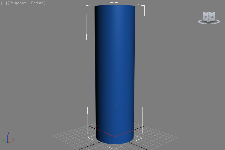
- Add a Genome modifier to the stack, set to “VERTEX” iteration mode.
- Press the “Open Magma Editor” button.
- Make sure the >AUTO UPDATE option is checked.
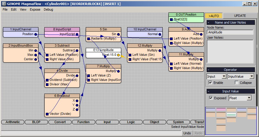
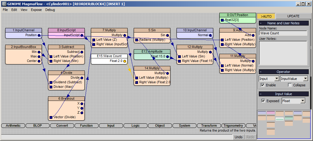
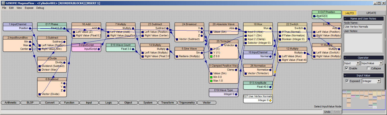
- Press Ctrl+[O] to create an Output node, set it to Position channel.
- Select the Output node and press SHIFT+[P] to create a Position InputChannel. Since we are outputting Position to Position, nothing really changes.
- Press Ctrl+[D] to Deselect All, then press [I] and [B] to create an InputBoundBox node.
The InputBoundBox node provides the Minimum, Maximum and Center values of the modifier’s bounding box. We will use them to normalize the Z position of the vertex along the Z axis of the Bounding box, thus producing the same effect regardless of the actual height of the incoming mesh.
- Select the Position InputChannel node.
- Note that it is selected to the Output node and the output socket and wire are highlighted. The title bar of the Editor says [INSERT 1]. This means that creating a new operator will insert it into the highlighted wire.
- Press the [Ins] key - the title bar will now read [CONNECT 1] which means that a new operator node will be connected with a NEW wire to the same output socket 1.
- Press the [-] key (minus key on Numeric Keypad) to create a new Subtract operator - it will be connected to the output of the Position channel input, but won’t be inserted into the existing wire!
- Drag a connection from the Min. output socket of the InputBoundBox to the Right Value input socket of the Subtract operator.
- Select the Subtract operator and press the [/] key on the Numeric Keypad to add a new Divide operator.
- Drag a connection from the Max. output socket of the InputBoundBox to the Divisor input socket of the Divide. The output of the Divide is now the normalized position of the Vertex (between [0,0,0] and [1,1,1]) relatively to the Modifier’s Bounding Box.
- With the Divide node selected, press [C] and then [B] to insert a Breakout conversion node. We will need only the Z component of the Vertex Position.
- Press Ctrl+[D] or click anywhere in the editor to deselect all.
- Press the [[] key (left rectangular bracket) to create a new Sin operator.
- Drag a connection from the Z output socket of the Breakout operator to the Radians input of the Sin operator.
Since the input expects Radians, but we are inputting a normalized value between 0.0 and 1.0, the function won’t produce the desired output (one full sine wave within the height of the bounding box gizmo). To solve this, we have to multiply the Z value by 2*Pi. We could multiply by 6.28 as approximation of 2*Pi , but we can get a much better value using a Script.
- Select the wire between the Breackout and the Sin operators and press the [*] key to insert a Multiply operator.
- With the Multiply operator selected, press [I] and [S] to create an InputScript node and connect it to the second socket of the Multiply.
- Enter 2*Pi in the Script text field.
- Select the wire connecting the Position InputChannel node to the Output node and press [+] on the Numeric Keypad to insert an Add operator.
- With the Add node selected, press SHIFT+[N] to create a Normal inputChannel and connect it to the second input socket of the Add operator.
- With the Normal inputChannel node still selected, press [*] to insert a Multiply operator.
- Drag a connection from the Sin operator’s output to the second input socket of the Multiply operator.
- Select the Sin operator and press [*] to insert another Multiply operator.
- Press Ctrl+[1] to connect a Float InputValue node to the second socket of the new Multiply operator. Check the “Exposed” option in the InputValue’s UI and change the value to 15.0. Rename the InputValue node to “Amplitude”
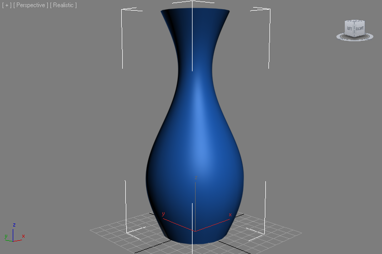
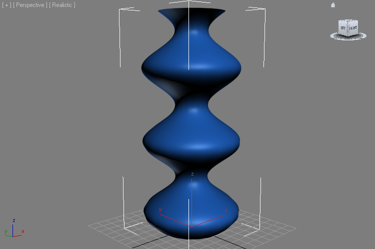
RESULT: At this point, the Cylinder should be deformed to a vase by a single sine wave along the Z axis. Note that the wave is in normalized space, so changing the Height of the Cylinder from 200.0 to 100.0 still produces exactly one wave! (right image)
Controlling The Wave Count
Let’s add a control for the number of waves within the bounding box along the Z axis.
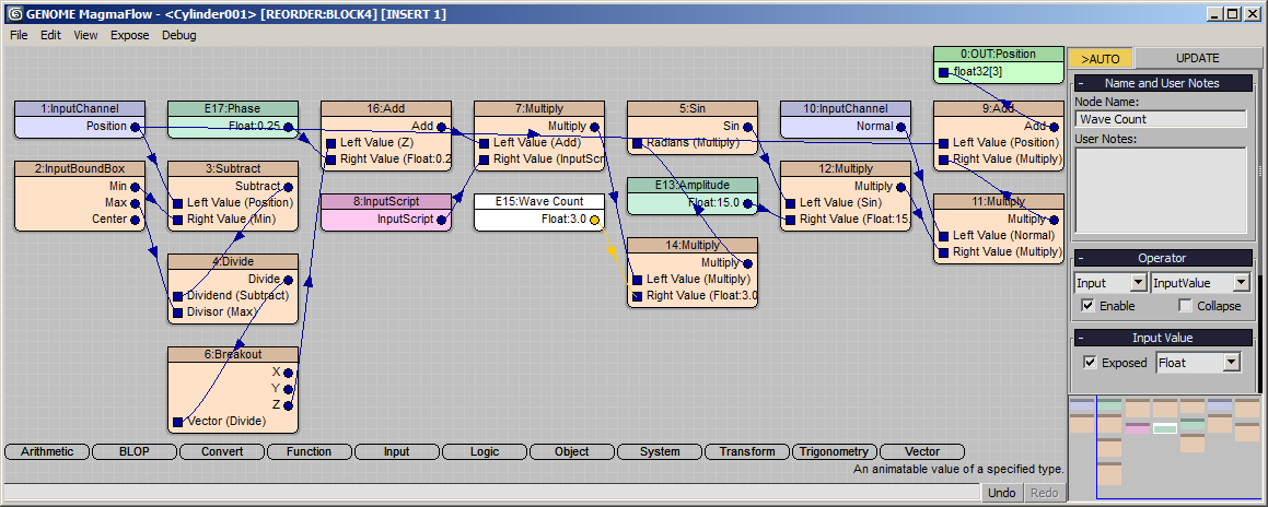
- Select the Multiply node before the Sin operator and press [*] to insert another Multiply operator.
- Press Ctrl+[2] to connect a Float InputValue node with a value of 2.0 to the second socket of the new Multiply.
- Rename the InputValue node to “Wave Count” and check the “Exposed” option in the UI.
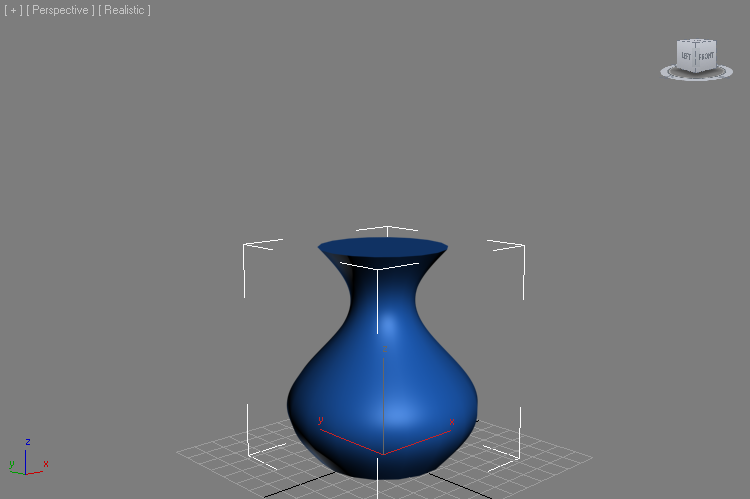
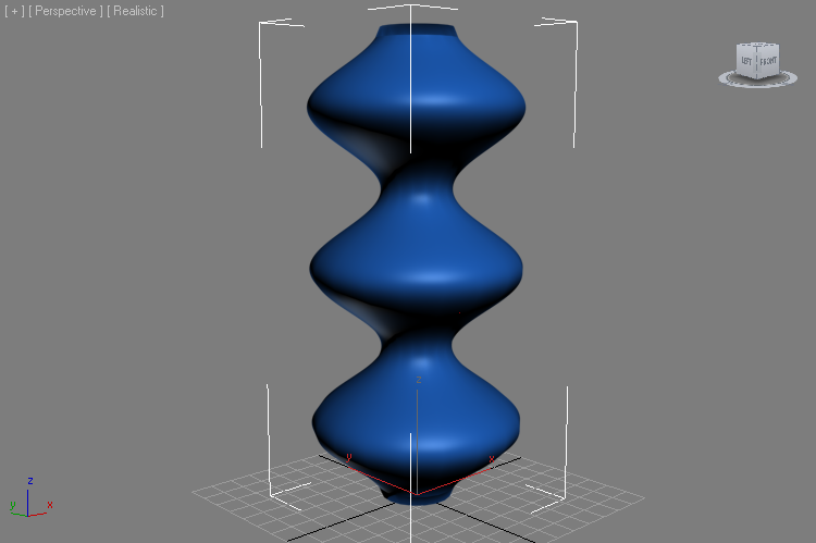
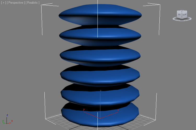
RESULT: The Cylinder now has two waves running along its Z axis (left image). If you change the Wave Count value to 3.0, there will be three waves (right image):

Controlling The Phase (Offset)
Right now, the wave starts with a value of 0.0 because Sin(0.0) is 0.0. We can easily add an offset value to the normaized Z coordinate.
- Select the Breakout operator and press [+] to insert an Add operator.
- Press Ctrl+[0] (zero on the top row of keys) to connect a Float InputValue node to the Add.
- Rename the node to “Phase” and check the “Exposed” option.
- Enter 0.25 in the Phase control.
RESULT: The top and bottom of the Cylinder are now pushed the same amount, with the second wave centered at half the height of the object.
Note that you can keyframe the Phase to animate over time and shift the wave along the Z.
Positive Wave Vs. Full Wave
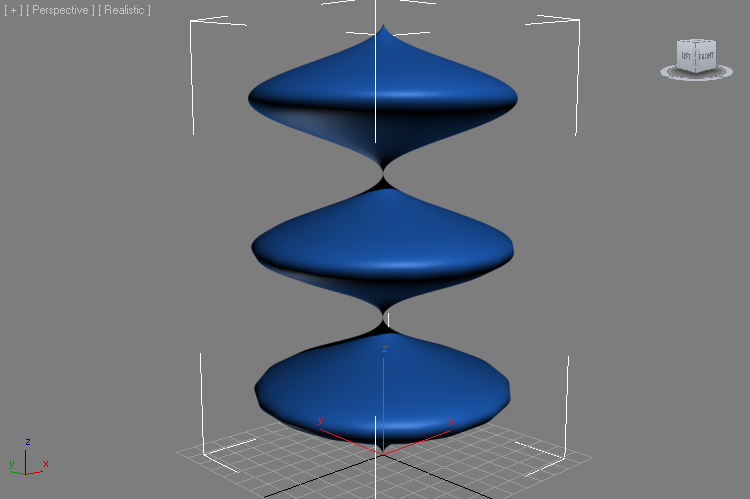
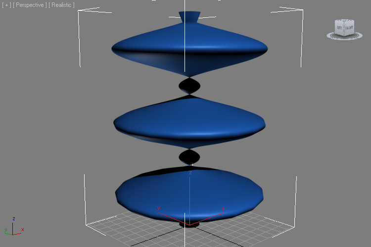
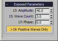
Currently, we use the full sine wave to push both outwards and inwards. Thus, using an Amplitude value higher than the Radius of the Cylinder would cause the mesh to self-intersect -the following images show Amplitudes of 30.0 and 40.0 (the Cylinder has a Radius of 30.0!):
It would be possible to calculate the distance from the center of the Bounding Box to its Maximum X and Y and prevent the self-intersection, but we won’t do this since it would reduce the flexibility of the modifier. (You can try to do it as an exercise though).
Bit we can add an option to the Modifier to use only positive values by calculating the Absolute value of the Sin operator.
- Select the Sin operator and press [L] and [W] to insert a Switch logical operator into the flow.
- Hold down Ctrl and click the Sin node again to add it to the selection. With both the Sin and the Switch selected, press [SPACEBAR] to connect the output of the Sin to the second input socket of the Switch.
- Select the Switch operator only and press 0 on the top row of the keyboard to create an Integer InputValue with value of 0.
- Rename the Integer InputValue to “Positive Waves Only” and check its “Exposed” option. Since it is connected to the Boolean control socket of the Switch operator, it will be exposed as a Checkbutton to the Command Panel!
- Select the wire connecting the Sin operator to the Switch and press [A] and then [B] to insert an Absolute operator.
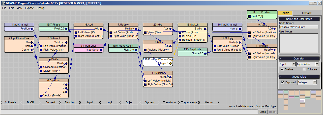
RESULT: At this point, checking the Positive Waves Only checkbutton in the 3ds Max Command Panel will turn the negative portion of the sine wave to positive, producing 6 waves out of 3:
Clamping The Negative Wave
Instead of reverting the negative to positive, we could also clamp the wave to the range from 0.0 to 1.0. But we don’t want to remove the already existing two options, so we will switch to a new control.
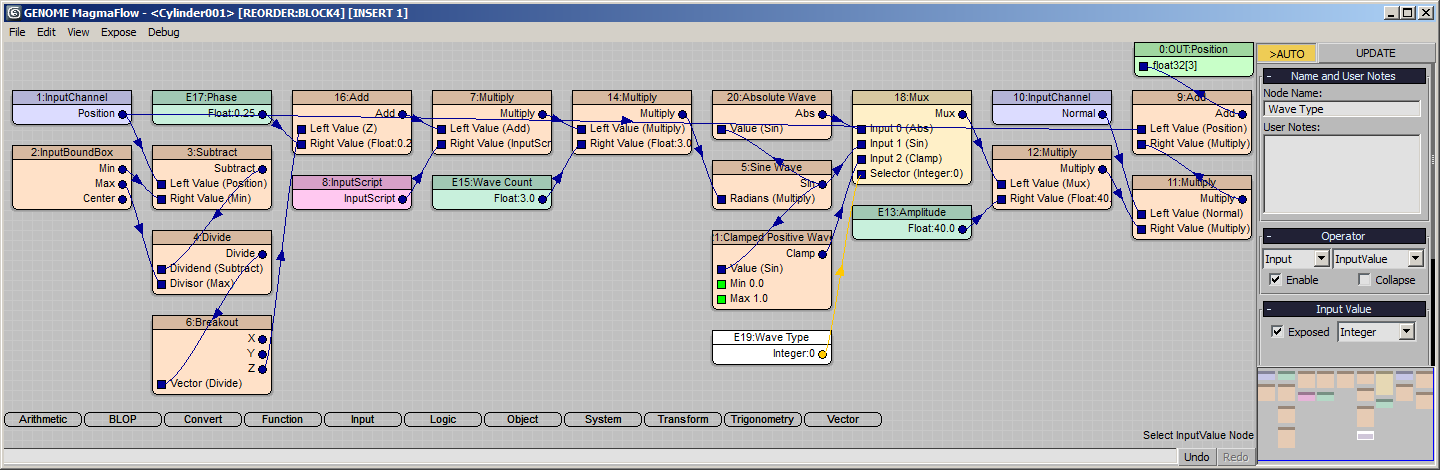
- Select the Switch operator and under the “Operator” rollout, change its type to from “Switch” to “Mux” (Multiplexor) using the drop-down list. All wires will be preserved, but the exposure in the Command Panel will be switched to a listbox with two entries, one for each input socket except the last (control) one.
- Select the Sin operator and rename it to “Full Sine Wave”.
- Select the Abs operator and rename it to “Absolute Wave”. Note that the listbox now shows the new names as entries.
- Select the Mux operator and change the Property “Number Inputs” from 3 to 4. This will introduce a new empty input socket and shift the control socket down.
- Hold down Ctrl and add the “Sine Wave” node (Sin operator) to the selection, then press [SPACEBAR] to connect the output of Sin to the new empty input socket of the Mux operator.
- Select the new wire between the Sin and the 3rd input socket of the Mux operator and press [F] and [C] to insert a Clamp function. It defaults to range from 0.0 to 1.0, just what we need.
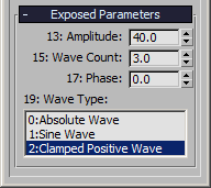
- Rename the Clamp function to “Clamped Positive Wave”. Note that the Command Panel will update to show 3 entries on the list.
- Select the Integer Input controlling the Mux operator and rename it to “Wave Type” to update the label in the Command Panel.
- Select the “Clamped Positive Wave” option from the list.
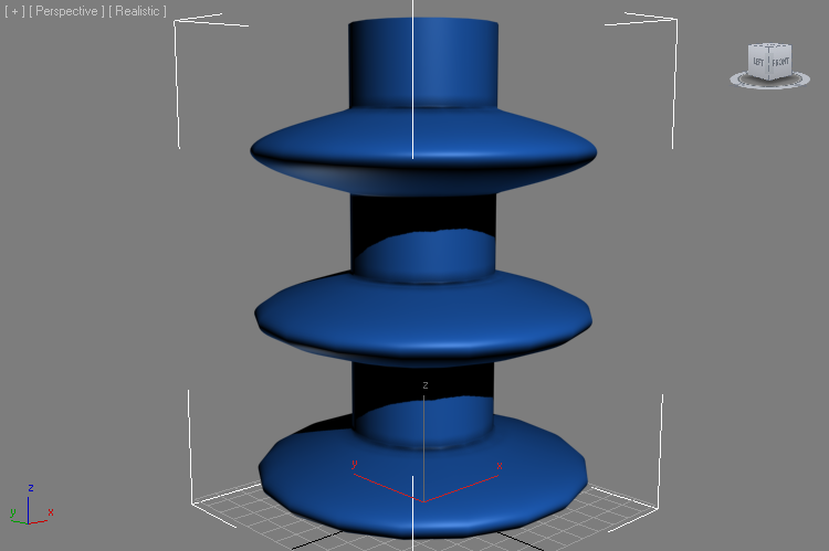
RESULT: The negative portions of the wave are now clamped to 0.0, reaving a flat undisplaced area between the positive waves!
Normal Displacement vs. Horizontal Displacement
The current version of the modifier uses the vertex normals to perform the displacement, just like the Push modifier does. But since the vertices at the edge of the Caps have normals that point half-way between the side the the cap, under certain conditions like a Phase of 0.25, the displacement might go in an unexpected direction:
Adding the option to push along the horizontal vector connecting the Center and the Vertex would be very useful when trying to produce a clean push outwards while ignoring the Caps’ influence.
- Select the Normal InputChannel node and press [L] and [W] to insert a new Switch operator.
- Drag a connection from the Position InputChannel node to the second socket (If False) of the Switch operator.
- Select the new wire between Position and Switch and press [-] to insert a new Subtract operator.
- Drag a connection from the Center output socket of the InputBoundBox operator to the second socket of the new Subtract operator.
- Select the Subtract operator and press [C] and [B] to insert a new Breakout operator.
- With the Breakout operator still selected, press [C] and [V] to insert a ToVector operator.
- The X is already connected, drag a connection from the Y output socket of Breakout to the Y input socket of the ToVector. Leave the Z input at default 0.0. This produces a horizontal vector from the Bounding Box Center to the Vertex Position.
- Select the ToVector operator and press [V] and [N] to insert a Vector > Normalize operator. This will give us a vector with length of 1.0, similar to the Normal vector, but always pointing outwards in the XY plane.
- Select the Switch operator with the missing 3rd input socket and press [0] to create a new Integer InputValue with value of 0. Rename to “Use Vertex Normals” and check the “Exposed” option.
RESULT: At this point, the modifier will push the vertices in the XY plane unless the checkbutton “Use Vertex Normals” is checked in the Command Panel:
Stacking The Modifiers
Now that we have the option to push either in XY plane or along the Normals, we can create some interesting displacements using multiple copies of this Genome Modifier on the same stack!
- In the 3ds Max StackView, select the Genome modifier, right-click and select Copy from the Menu.
- Right-click again and select Paste.
- Change the new copy’s “Amplitude” to 10.0 and check “Use Vertex Normals”.
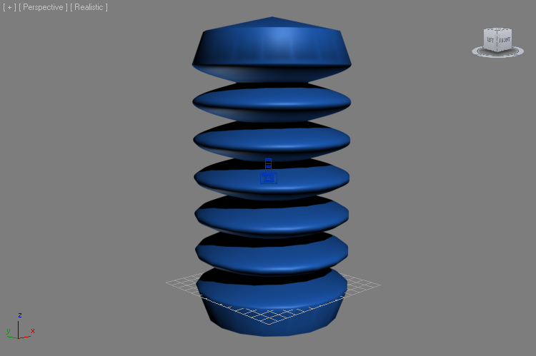
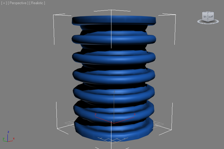
RESULT: We now have two waves on top of each other. Both have the same Phase and Wave Count, but the second wave displaces along the normals which were deformed by the first wave.
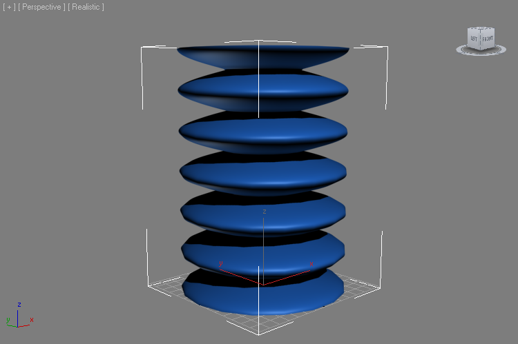
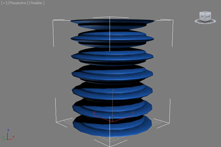
Change the top modifier’s Wave Count to 9.0, leave the Phase at 0.25 (left image). Then uncheck the “Use Vertex Normals” (right image):
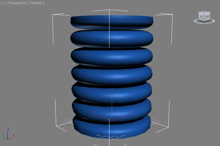
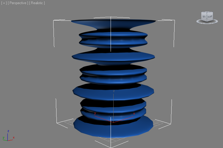
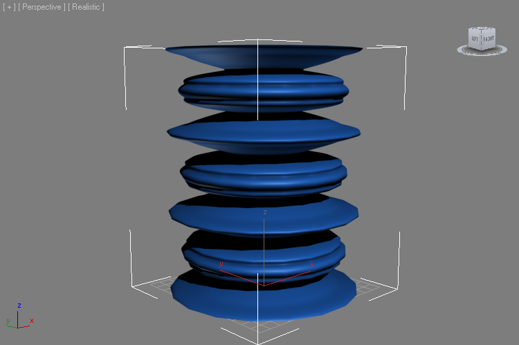
Change the Wave Type of the top modifier to “Sine Wave” (left image) and then to “Clamped Positive Wave” (right image):
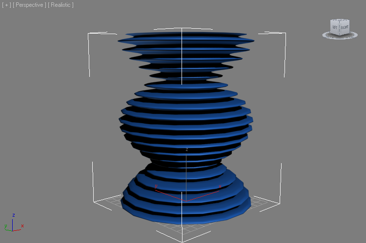
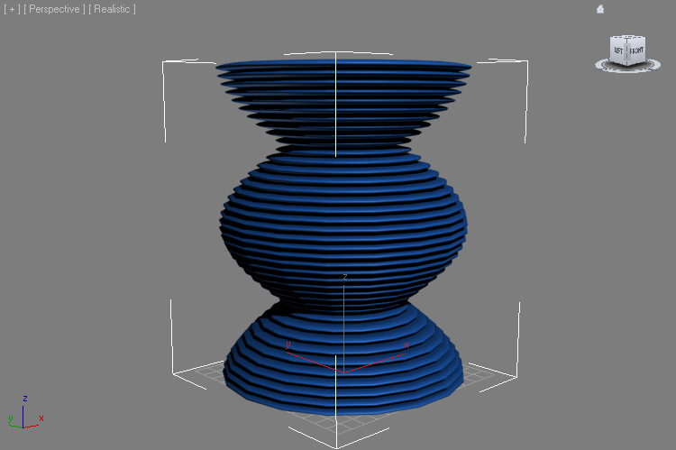
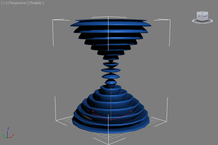
Go down to the second Genome modifier and change it to Wave Count of 1.0 (Amplitude 40.0, Phase 0.25, Absolute Wave).
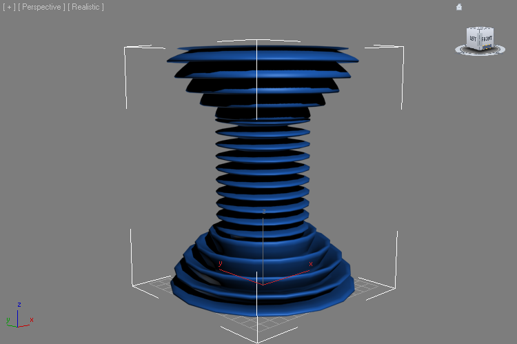
Then go back to the top Genome modifier and change it to Wave Count of 20.0 (Amplitude 10.0, Phase 0.25) and switch the Wave Type To “Sine Wave” (left image). Switching to “Absolute Wave” will produce an even finer rippling on top of the base wave (right image):
Checking the “Use Vertex Normals” option of the top Genome modifier again will shift the vertices according to the already deformed surface coming from the bottom Genome modifier, producing other interesting effects.
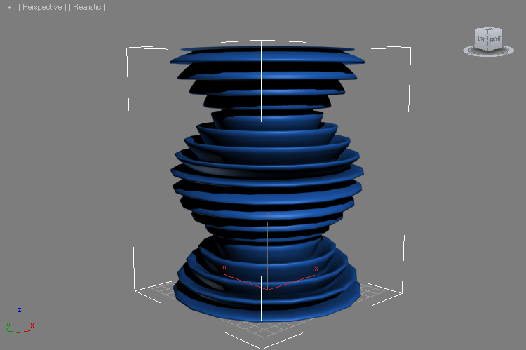
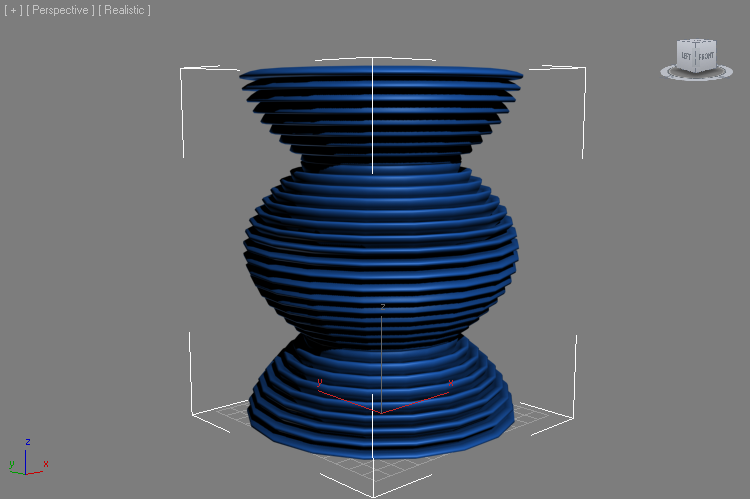
Switching the bottom modifier to “Sine Wave” mode (left image) and “Clamped Positive Wave” produces the following results:
There are many interesting combinations of multiple waves. Also remember that all parameters exposed to the UI are animatable over time. Experiment with the settings to discover new forms and effects!
Bulge Deformations and Other Modifiers
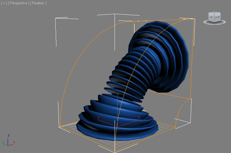
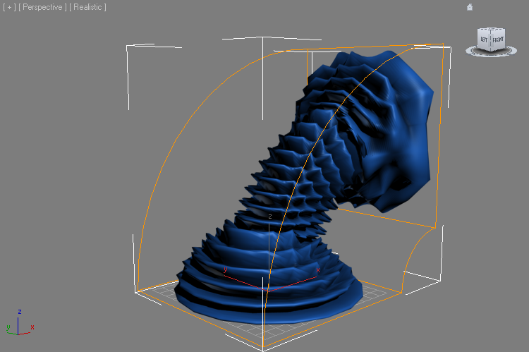
The Bulge modifier was designed to be used mostly on tall objects along their Z axis. As with all modifiers, the order of deformations matters. For example, a Bend modifier can be added to the stack after the Bulge and it will deform the already rippled object:
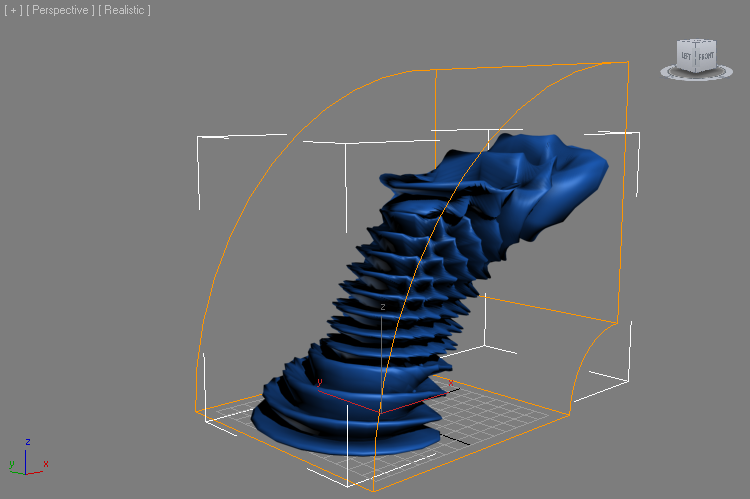
Moving the Bend before the two Genome modifiers (left image) or between the first and the second (right image) will apply the bending deformation first, and the following Bulge deformation will be performed on the result:
Next Topic:
Screw Deformation Modifier (Bulge Continued…)