Conform To Surface Modifier
3ds Max provides a Conform Space Warp which can be used to project the vertices of an object to the surface of another object along a specified vector. Unfortunately, this implementation is very slow with high-resolution meshes and can be used dynamically only with low-resolution ones.
Performance Comparison
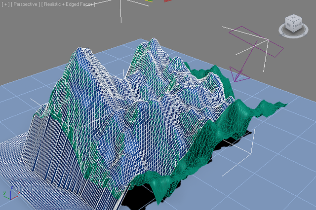
In the following example, a recrangular terrain contains only triangle faces. The mesh has 12,066 faces:

Using the 3ds Max Conform Space Warp
In order to produce the same terrain as quads, we could conform a Plane primitive to it. The Conform Space Warp provides a projection direction and a stand-off distance, by default 1.0 unit above the original surface.
Using 50x50 segments on the Plane (2601 vertices), it takes around two seconds to conform the plane to the original mesh using the native Conform Space Warp’s brute force approach.

But increasing the segments to to 100x100 (10,201 vertices) also increases the conform time to over 7 seconds.

It makes sense that increasing the face count four times would cause a four times performance decrease, since the 3ds Max Conform checks every vertex against every face of the target surface.
Using the Genome Conform modifier
In contrast, the Genome version of the Conform modifier operates instantly. In fact, it is faster to conform 1000x1000 segments (1,002,001 vertices) with the Genome modifier than 50x50 (2601 vertices) with the native Space Warp! See the video below to witness the difference:
Creating the Genome Conform Modifier
- Create a Plane with size slightly below the target mesh’s size (in this example, the target mesh had a size of 120.0x120.0 units, the Plane was set to 119.9x119.9 to avoid missing the intersections at the edges/corners.
- Add a Genome modifier, set to “VERTEX” iteration mode.
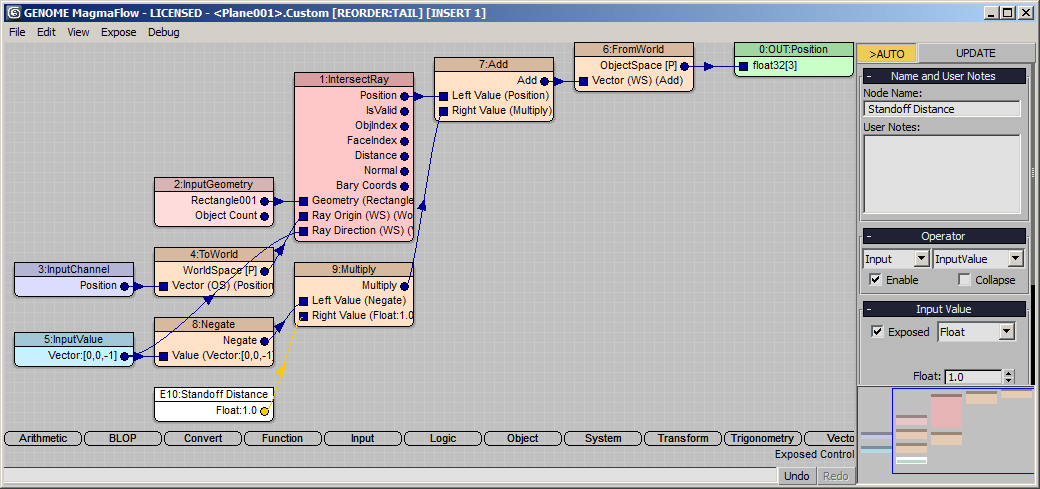
- Open the Magma editor and press Ctrl+[O] to create an Output node, set it to Position channel.
- Click in the editor to deselect, then press [O] and [R] to create an IntersectRay operator.
- Drag a wire from the Geometry socket and release over an empty area to create an InputGeometry node.
- Pick the terrain mesh as the Geometry input object.
- Drag a wire from the Ray Origin (WS) socket and release over an empty area to create a Position InputChannel with a ToWorld transform operator.
- Drag a wire from the Ray Direction (WS) socket, then press and hold Ctrl and release to create a Vector InputValue with a default value of [0,0,-1]. (Not holding Ctrl would open the general operators menu with all options, holding Ctrl produces a negative Z axis vector for cases like this)
- Connect the Position output of the IntersectRay with the Output node.
- Select the IntersectRay node and press [T] and [W] to insert a FromWorld operator in the new wire since the ray intersection result comes in world space, but we want it in object space.

RESULT: The plane is now moved down to the surface of the target mesh.
Implementing The Standoff Distance Control
- Select the IntersectRay again and press [+] to inser an Add operator.
- Drag a wire from the Vector InputValue connected to the Ray Direction socket.
- Select the new wire and press [A] and [N] to insert a Negate operator becaise we want to move in the opposite direction of the projection vector.
- With the Negate node selected, press [*] to insert a Multiply operaotor.
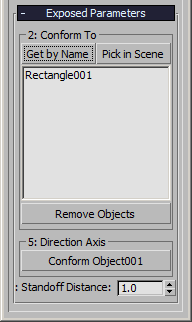
- Press Ctrl+[1] to connect a Float InputValue with value of 1.0. Rename it to “Standoff Distance” and check the “Exposed” option.
RESULT: The new positions are now one unit above the target surface.
Checking Intersection For Validity
Now we should ensure the vertices are only moved if a valid intersection could be found.
- Select the FromWorld operator and press [L] and [W] to insert a Switch operator.
- Connect the Position InputChannel to the second socket (If False).
- Connect the IsValid output socket of the IntersectRay to the third (Boolean) socket.
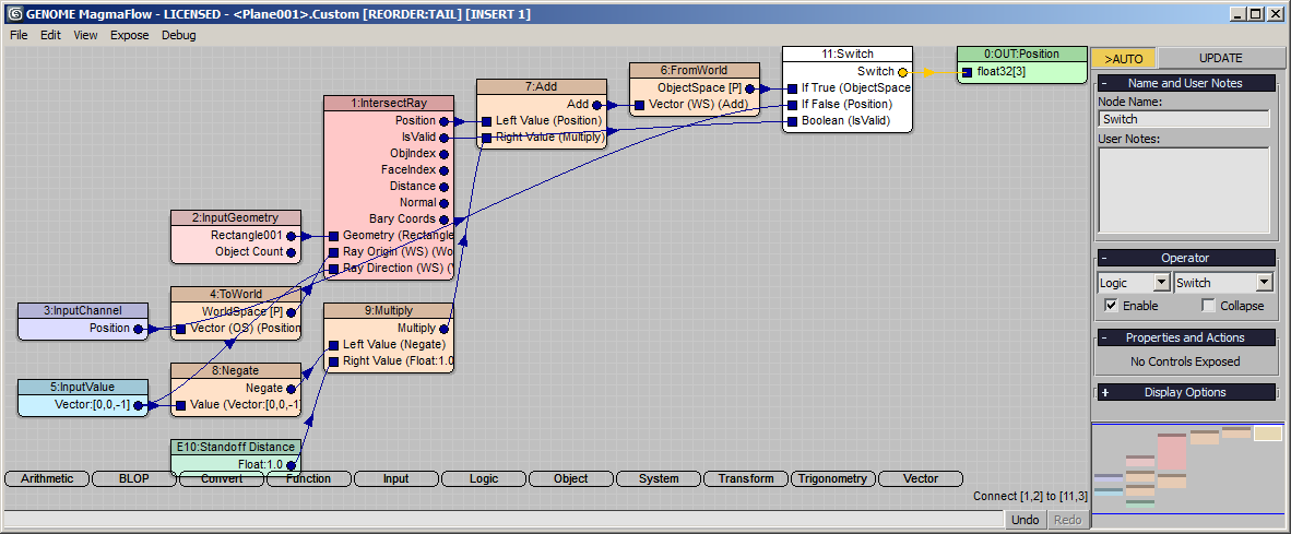
RESULT: Now, the intersection position will only be set if a valid intersection was detected, otherwise the vertex will remain where it was.
Using Projection Axis Reference Object
The native Conform Space Warp of 3ds Max uses its Negative Z axis to define the projection direction. We can implement an external reference object in our Genome modifier version by reading the Z axis of any scene object (in this case, even the Conform Space Warp itself, since it has a nice large arrow!).
- Select the Vector InputValue node and change its type to InputObject.
- Rename the node to “Direction Axis” and check the “Exposed” option.
- Rename the InputGeometry node to “Conform To” and check its “Exposed” option, too.
- Pick the “Conform Object001” in the scene, or create and use a Point helper or any other scene object.
- Select the InputObject node and press [O] and then [E] to insert a PropertyQuery operator.
- Enter “transform.row3” in the text field and press Enter to add as a new output socket.
- Select the “pos” entry from the list and press the “Remove…” button - the new “transform.row3” socket will become output one and will be connected to the other nodes!
- Since we are reading the POSITIVE Z axis (row3 of the node transformation matrix of the reference object), we will have to revert some wires - we will connect the Negate node to the Ray Direction (WS) socket of the IntersectRay, and the PropertyQuery itself to the Multiply node for the Standoff Distance value.
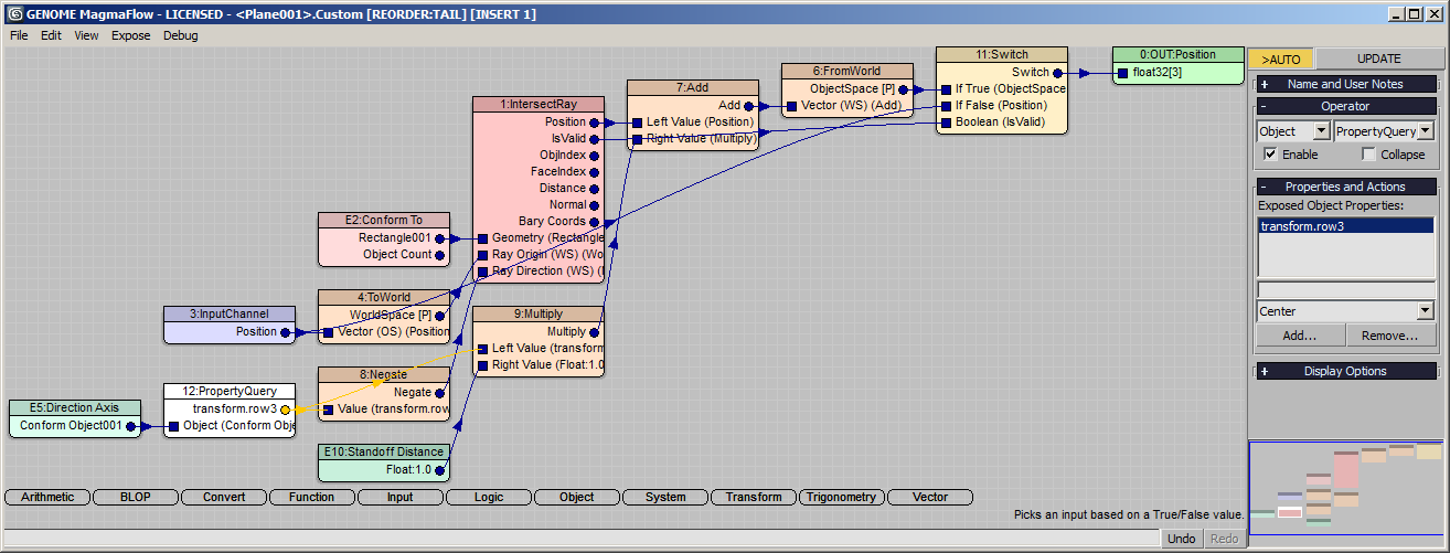
RESULT: At this point, rotating the Conform Object’s Arrow icon will also change the projection direction of the Genome modifier.

Using Multiple Targets
Another benefit of the Genome implementation of the Conform modifier is the ability to project against an arbitrary number of meshes - the first intersection will be taken into account.
In the case of the rotated projection vector, we could benefit from having another larger object as “background” of the terrain to provide valid intersections beyond the original terrain mesh.
In this case, we will create a simple Plane, but we could use any number of other meshes to test…