Krakatoa MY PRT Surface
- The PRT Surface object allows the quick conversion of a polygon mesh surfaces to a point cloud.
- It is available in Krakatoa MY v2.3.0 and higher.

- The Krakatoa MY Installer creates a Krakatoa shelf in the Autodesk Maya User Interface and places several icons on it, including a PRT Surface icon.
- Pressing the PRT Surface icon will create a new PRT Surface object at the world origin. You will have to connect it to a mesh, align it and set up the viewport spacing manually or via the Mesh Input Advanced Tools panel buttons.
- Selecting a mesh object in the view and the pressing the PRT Surface icon will create a new PRT Surface object aligned to the selected mesh, and rename the PRT Surface object to match the name of the mesh object.
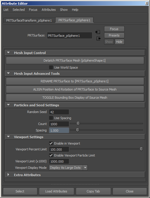
Random Seed value
- Default is 42.
- This value defines the random seed to use when generating random particles within each polygon.
- A specific seed value guarantees a consistent random pattern over time.
- For the cases where the random pattern should be inconsistent, this value can be animated.
Use Spacing checkbox
- When unchecked (default), the Count value will be active and will define the total number of particles to generate.
- When checked, the Count value will be grayed out and the Spacing value will become available. allowing you to define the distance between the seeded particles.
Count value
- This value defines the number of particles to generate accross the whole surface..
- It is only active and used when the “Use Spacing” checkbox is unchecked.
Enable in Viewport checkbox
- Default is checked.
- When checked, the PRT Surface particles will be drawn in the viewport.
- When unchecked, the PRT Surface particles will not be drawn, but they will still be rendered.
Viewport Percent Limit value
- Default is 100.0 percent.
- This value defines the percentage of particles to be drawn in the viewports.
- This value can be used to draw a fraction of the particles normally scheduled for display.
Enable Viewport Particle Limit checkbox
- When checked (default), the “Viewport Particle Limit” will be enforced and only up to that number of particles will be drawn in the viewports.
- When unchecked, any number of particles requested by the controls above will be allowed.
Viewport Particle Limit value
- Default is 1000.0 (equivalent to 10,000)
- This value defines the number of particles (in thousands) to be drawn in the viewports.
- Once this value is reached, the viewport drawing will stop.
- This is meant as a precaution since a PRT Surface with small spacing or a very high count could potentially produce hundreds of millions of particles and slow down viewport redraws significantly.
Viewport Display Mode list
- Display as Small Dots - When selected, the particles will be drawn as one-pixel-sized points.
- Display as Large Dots - default. When selected, the particles will be drawn as large dots.
- Display Velocity - This is currently not used.
- Display Normals - When selected, the particles will be drawn as lines representing the surface’s normal vectors as sampled by the particles.