Krakatoa MY PRT Volume
- The PRT Volume object allows the quick conversion of a polygon mesh volume to a point cloud.
- The Krakatoa MY Installer creates a Krakatoa shelf in the Autodesk Maya User Interface and places several icons on it, including a PRT Volume icon.
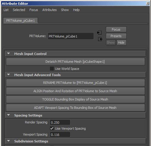
- Pressing the PRT Volume icon will create a new PRT Volume at the world origin. You will have to connect it to a mesh, align it and set up the viewport spacing manually or via the Mesh Input Advanced Tools panel buttons.
- Selecting a mesh object in the view and the pressing the PRT Volume icon will create a new PRT Volume aligned to the selected mesh, rename the PRT Volume to match the name of the mesh object, and change the Viewport Spacing to a suitable value to avoid producing too many or too few particles.
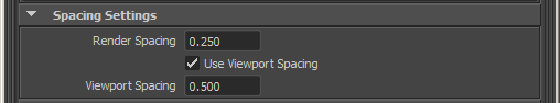
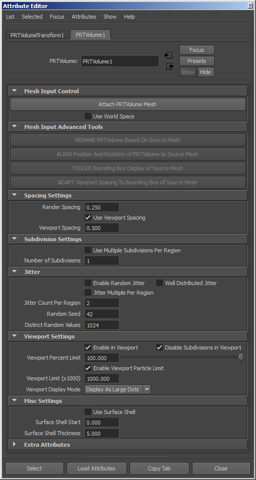
Render Spacing value
- Default is 1.0
- This value defines the voxel grid spacing. PRT Volume creates a LevelSet of the mesh using the Spacing value, then places one or more particles in each voxel.
Use Viewport Spacing checkbox
- Default is checked.
- When checked, the separate “Viewport Spacing” value will be used for the viewports, thus decoupling the grid resolution from the render-time spacing.
- When unchecked, the “Render Spacing” value will be used for both rendering and viewports. This can be dangerous when generating millions of particles if the viewport limits are not enabled!
Viewport Spacing value
- Default is 2.0
- When the “Use Viewport Spacing” checkbox is checked, this value defines the grid spacing for the viewport.
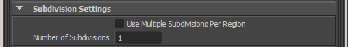
Use Multiple Subdivisions Per Region checkbox
- Default is checked
- When checked, each voxel will be subdivided according to the “Number Of Subdivisions” value - 1 subdivision produces 2x2x2 = 8 sub-regions.
- When unchecked, the voxels generated by the LevelSet will be used.
Number Of Subdivisions value
- Default is 1
- See above for details.
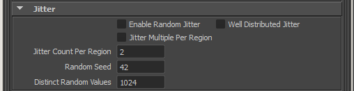
Enable Random Jitter checkbox
- Default is unchecked
- When unchecked, a single particle will be placed in the center of each region (voxel, or voxel subdivision)
- When checked, one or more particles (depending on the settings below) will be placed randomly within each region.
Well Distributed Jitter checkbox
- Default is unchecked.
- When unchecked, the distribution of the particles within the region will be fully random, based solely on the Random Seed. This means that clumping, esp. at the borders of the regions might occur (more particles in one place than another).
- When checked, a number of tileable random patterns will be calculated for the amount of particles defined in the “Random Count” field. These patterns guarantee that the distribution will be spatially uniform and no clumping could occur at the borders of the regions.
- This option is ignored when “Enable Random Jitter” is unchecked
- Note that the calculation of pre-defined patterns can take time and this mode is generally slightly slower than pure random distribution.
Jitter Multiple Per Region checkbox
- Default is unchecked.
- When unchecked, only one random particle will be created per region when “Enable Random Jitter” is checked.
- When checked, the “Jitter Count Per Region” value will determine the number of particles to distribute randomly in each region when “Enable Random Jitter” is checked.
- This option is ignored when “Enable Random Jitter” is unchecked.
Jitter Count Per Region value
- Default is 2
- This value determines the number of random particles to distribute within each region when both “Enable Random Jitter” and “Jitter Multiple Per Region” are checked.
Random Seed value
- Default is 42
- This value defines the random seed to use when generating random particles within each region.
- A specific seed value guarantees a consistent random pattern over time.
- For the cases where the random pattern should be inconsistent (random noise over time, for example to simulate the changing pattern of foam particles in a fluid simulation), this value can be animated.
Random Count value
- This value defines the number of pre-defined random positions in the random patterns generated in “Well Distributed Jitter” mode.
- The “Jitter Count Per Region” value should not exceed the Random Count value. If you need more than the Random Count particles per region, be sure to increase the value.
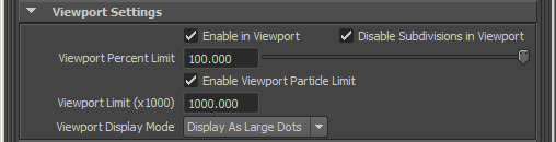
Enable in Viewport checkbox
- Default is checked.
- When checked, the PRT Volume particles will be drawn in the viewport.
- When unchecked, the PRT Volume particles will not be drawn, but they will still be rendered.
Disable Subdivisions in Viewport checkbox
- Default is checked.
- When checked, subdivision settings will be ignored in the viewports to avoid the generating of potentially millions of particles.
- When unchecked, all particles scheduled for rendering will also be drawn in the viewport, up to the “Viewport Percent Limit” value.
Viewport Percent Limit value
- Default is 100.0 percent.
- This value defines the percentage of particles to be drawn in the viewports.
- This value can be used to draw a fraction of the particles normally scheduled for display.
Enable Viewport Particle Limit checkbox
- When checked (default), the “Viewport Particle Limit” will be enforced and only up to that number of particles will be drawn in the viewports.
- When unchecked, any number of particles requested by the controls above will be allowed.
Viewport Limit (x1000) value
- Default is 1000.0 (equivalent to 1,000,000 particles)
- This value defines the number of particles (in thousands) to be drawn in the viewports.
- Once this value is reached, the viewport drawing will stop.
- This is meant as a precaution since a PRT Volume with small voxel size or from a very large mesh could potentially produce hundreds of millions particles.
Viewport Display Mode list
- Display as Small Dots - When selected, the particles will be drawn as one-pixel-sized points.
- Display as Large Dots - default. When selected, the particles will be drawn as large dots.
- Display Normals - When selected, the particles will be drawn as lines representing the surface’s normal vectors as sampled by the particles.
Use Surface Shell checkbox
- Default is unchecked.
- When unchecked, the complete volume of the mesh will be filled with particles.
- When checked, particles will be distributed only within the range defined by the “Surface Shell Start” and “Surface Shell Thickness” values.
Surface Shell Start value
- Default is 0.0.
- Used only when “Use Surface Shell” is checked.
- This value defines the beginning of the particle volume relatively to the inside surface of the geometry. Positive values move the beginning of the range towards the center of the volume.
- If the value is less than the largest distance to the surface in the volume, no particles will be generated regardless of the “Surface Shell Thickness” value.
- Animating this value from a high value towards 0.0 can thus produce a “growing from the center” effect; animating from 0.0 to a positive value can produce a “shrinking towards the center” effect.
Surface Shell Thickness value
- Default is 5.0.
- Used only when “Use Surface Shell” is checked.
- This value defines the thickness of the region relatively to the inside of the “Surface Shell Start” value.
- A value of 0.0 will produce no particles regardless of the Start value.
- Increasing this value will make the shell thicker.
- Animating this value can produce thinning out or solidifying shell effects.