Transforming Objects
- Objects can be transformed using one of the following approaches:
- Interactive transformations using the on-screen Gizmos,
- Manual entry via the numeric input fields of the Transformations panel
- Quick transformations via the Transform Preset operations in the Transformations panel’s
Options menu.
Interactive Transformations
- By default, SEQUOIA will be in SELECT Tool mode, represented by an Arrow icon.
- To switch to one of the Transformation modes, you can either:
- Click on the MOVE Tool, ROTATE Tool or SCALE Tool icon in the Transform Tools Toolbar.

- Right-Click in a viewport and select the MOVE Tool, ROTATE Tool or SCALE Tool menu item from the Transformations menu (right-most icon).
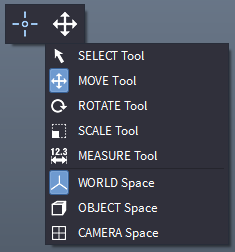
- Press the 2, 3 or 4 key to switch to Move, Rotate or Scale Tool mode.
- You can press the 1 key to switch back to SELECT Tool mode.
- Once a Transform Tool mode is enabled, a corresponding Move, Rotate or Scale gizmo will be drawn in the viewport.
- It will be placed at the object’s Pivot Point and will be aligned to the current Reference Coordinate System.
- Both the Pivot Point location and the Reference Coordinate System can be set by the user.
Reference Coordinate Systems
- The Reference Coordinate System defines the orientation of the X, Y and Z axes used to perform the Move and Rotate transforms. (Scaling is always performed in Object space.)
- Sequoia provides three reference coordinate systems:
WORLD Space
- The X, Y and Z transformations axes of the Move and Rotate Tools will always be aligned to the world X, Y and Z axes.
- Rotating the object will NOT change the orientation of the Move and Rotate gizmos.
- The Scale Gizmo is always in Object Space and is not affected by this mode.
OBJECT Space
- The transformation axes will be aligned to the object’s local coordinate system.
- Rotating the object will affect the orientation of the Move, Rotate and Scale gizmos.
CAMERA Space
- The transformation axes of the Move and Rotate Tools will be aligned to the current view’s camera axes.
- The +X will always point horizontally to the right of the screen
- The +Y will always point up,
- The +Z will point towards the viewer.
- The Scale Gizmo is always in Object Space and is not affected by this mode.
Using The Move Gizmo
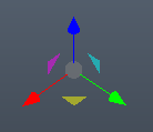
- The Move Gizmo consists of three arrows at 90 degrees to each-other representing the axes of the current Reference Coordinate System, three planar handles in the shape of triangle representing the three planes defined by axes pairs, and a circle for free screen space transforms.
- To move an object along a single axis, Left-Click and hold on the corresponding red (X), green (Y) or blue (Z) arrow of the gizmo and drag along the arrow.
- To move an object within the plane defined by two axes, Left-Click and hold on the corresponding triangular plane handle - yellow (XY), magenta (XZ) or cyan (YZ) - and drag with the mouse.
- To move in screen space regardless of the current reference coordinate system, Left-Click and hold on the gray sphere at the root of the gizmo.
- To snap the move gizmo to round increments, hold down the SHIFT key.
- The default Snap increment is 10 units, but it will adjust adaptively based on the overall size of the object’s bounding box - smaller objects can snap to 1 unit.
Using The Rotate Gizmo
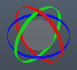
- The Rotate Gizmo consists of three rings at 90 degrees to each-other representing the three axes of the current Reference Coordinate System, as well as a sphere for free 3D transformations.
- To rotate an object about a single axis, Left-Click and hold on the corresponding red (X), green (Y) or blue (Z) ring of the gizmo and drag the mouse.
- The rotation angle will be represented in yellow as a segment between two lines - one line will be fixed, the other will rotate as you move the mouse.
- The behavior of the rotation gizmo will depend on the current Controls mode defined in the Options menu:
STANDARD Controls Rotation
- Linear motion of the mouse is interpreted as tangential motion and increases the rotation angle continuously.
ALTERNATIVE Controls Rotation
- The second, dynamic line defining the angle will always pass through the mouse pointer.
Angle Snapping
- Holding down the SHIFT key will snap the rotation angle to 5 degrees, allowing the easy rotation at round angles like 15, 30, 45, 60, 90 etc.
Free Rotation
- To rotate an object freely in 3D, Left-Click and hold on the gray sphere at the root of the gizmo.
- Moving the mouse up and down will rotate about the camera’s X axis, moving the mouse left and right will rotate about the camera’s Y axis.
- The SHIFT key snap will be ignored in this mode.
- The Angle displayed in the readout will be relative to the Camera’s Z axis.
Using The Scale Gizmo
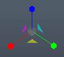
- The Scale Gizmo consists of three axes with boxes at their ends at 90 degrees to each-other, presenting the X, Y and Z axes of the Object Coordinate System, as well as a gray circle for Uniform scaling at the base of the gizmo.
- Note that the Scale Gizmo is always in Object Reference Coordinates to avoid the skewing of the object transformation matrix (which would result in non-orthogonal X,Y and Z axes).
- To Scale non-uniformly along a single axis, Left-Click and hold on the respective red (X), green (Y) or blue (Z) axis, then drag with the mouse to scale.
- To Scale uniformly along all three axes, Left-Click and hold on the gray circle at the center of the gizmo and drag the mouse horizontally to the right to scale up, and to the right to scale down.
- Hold down the SHIFT key while scaling to snap to round scale values.
Transforming Multiple Objects At Once
- When multiple objects are selected (by holding down the CTRL key when clicking to add to the current selection), the Transform Gizmo will be displayed only at the Pivot of the first selected object.
- All further selected objects will be transformed about their own Pivots using the exactly same values provided by the Gizmo for the first object.
- Currently, there is no way to transform a multi-object selection as one object with a common pivot point.
Pivot Point Placement
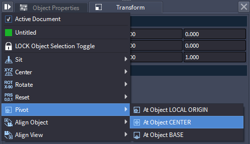
- The pivot point represented by the Gizmo and by the numeric values shown in the Transformations panel can be set to the Local Origin, Bounding Box Center or Bounding Box Base of the Object using the Options Menu of the Transform panel.
- Local Origin - (default) - the transformation point will be assumed at the local 0,0,0 point of the object. This is the location where the object’s icon would be drawn if no point or mesh data exists, and where a particle or vertex with coordinates of 0,0,0 would be drawn if the object is not transformed.
- Bounding Box Center - the transformation point will be assumed at the center of the Bounding Box determined from the min. and max. point or vertex values if data is loaded. Since very often the point data loaded has values far away from the 0,0,0 origin, this mode allows you to transform an object based on where the data actually is as opposed to where the object’s origin is.
- Bounding Box Base - the transformation point will be assumed at the base of the Bounding Box determined from the min. and max. point or vertex values if data is loaded. This makes it easier to set an object at the ground plane by simply entering 0 for the Z component.
- Note that each time you set the Pivot to a new position, the current Transforms will be baked implicitly into the Transformation Stack of the object.
- See the topic Transformation Stack Rollout for details.
Transformation Rollout Numeric Input
- When an object is selected, you can enter absolute values for its World Space Position and Rotation, and Object Space Scale using the fields in the Transformation rollout of the Transform Panel.
Preset Transformations
- The Options Menu accessible via the icon of the Transform panel provides access to the following Transformation presets:
- SIT At Origin - pick this option to set the X and Y components of the pivot point of the current selection to 0, and the bottom of the bounding box to the ground plane.
- SIT At Ground Plane - pick this option to set the bottom of the bounding box of the selected object to the ground plane without affecting the X and Y. This will affect only the Z component of the Position.
- CENTER At Origin - pick this option to move the center of the bounding box of the selected object to the World Origin 0,0,0.
- CENTER X at Origin - pick this option to change the X component of the selected object’s Position to 0.
- CENTER Y at Origin - pick this option to change the Y component of the selected object’s Position to 0.
- CENTER Z at Origin - pick this option to change the Z component of the selected object’s Position to 0.
- ROTATE X by -90 Degrees - pick this option to rotate the selected object about the X axis at -90 degrees.
- RESET - pick this option to reset the whole world transformation matrix to the identity matrix - Rotation of 0.0, Scale of 1.0 and Position of 0.0.
- RESET Position - resets the translation component to 0.
- RESET Scale - reset the scaling component to 1.
- RESET Rotation - reset the rotation component to 0.
Automatic Data Transformation Based On Metadata
- When loading point data from some file types like PRT 1.1, the metadata stored in the file will allow the Point Loader to adjust the transformations on the fly and orient the point cloud correctly even if the data comes from an application with a different (e.g. Y-up) coordinate system.
- If the point data comes from a source that does not provide such metadata, you might have to apply additional transformations (rotation and possibly scale) to adjust the alignment.