Stoke Atmospheric Effect
Available in Stoke MX 2.0 and higher. Last Edited June 3, 2014
Introduction
Stoke MX 1 relied completely on other tools for the rendering of its results - you had the choice of rendering the PRT files it produced as points or voxels in Krakatoa, as meshes in any geometry renderer via Frost, or via Particle Flow and the Krakatoa PRT Birth and Update operators.
Stoke MX 2 adds a dedicated volumetric rendering component which allows Stoke Fields to be rendered in any renderer that supports the 3ds Max Environment Atmospheric effects system. These renderers include the Default Scanline renderer of 3ds Max, Chaos Group V-Ray, and Cebas finalRender. Note that mental ray and iRay are not supported because they use an incompatible shading system.
The Stoke Atmospheric effect is very similar to the Krakatoa MX 2 Atmospheric effect, except that the former renders Field data directly, while the latter renders particle data.
Benefits And Limitations
The Stoke Atmospheric effect provides the following benefits:
- Fields can be rendered in the compatible renderers listed above without the need for any other 3rd party tools like Krakatoa, FumeFX etc.
- The Atmospheric effect integrates fairly well with the scene by casting and receiving shadows on/from scene geometry, appearing in reflections and refractions etc.
- It supports the typical Krakatoa shading channels including Density, Color, Emission and Absorption, as well as separate global Camera, Lighting and Emission controls.
The Stoke Atmospheric effect has the following known current limitations:
- It does not support several renderes shipping with 3ds Max - mental ray, iRay, Quicksilver.
- It is generally slower than some alternative solutions, esp. when used with the Default Scanline renderer.
- It does not support all possible atmospheric-related features if 3ds Max, for example the Atmospheric Shadow Opacity parameter of Lights is currently ignored.
- It does not support advanced rendering features like for example multiple scattering available in other solutions.
User Interface
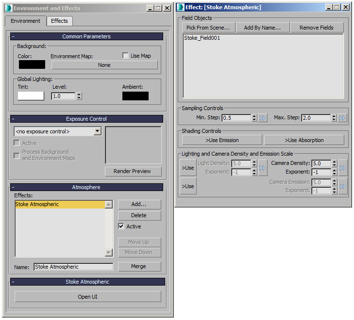
Field Objects group of controls
Pick From Scene… button
- Press to pick a Stoke Field source object from the scene by clicking in the viewports.
- Only valid Stoke Field objects can be picked.
- Right-click to cancel.
Add By Name… button
- Press to add one or more Stoke Field source objects from a list.
- Only valid Stoke Field objects can be picked.
- Right-click to cancel.
Remove Fields button
- Highlight one or more Field Objects on the list and press this button to remove them to exclude them from rendering.
- Note that most Stoke Field objects are created as non-renderable but will still render when picked by a Stoke Atmospheric effect.
Sampling Controls group of controls
Min. Step value spinner and preset button
- Defines the minimum distance a ray can step through the volume, in generic units.
- Default value is 0.5.
- This value can only be less or equal to the Max. Step value. If the Max. Step value is reduced below the Min. Step value, the latter will be automatically adjusted to be equal.
- Use the Preset [>>] button to set to a pre-defined value, or to manage preset values for future use.
Max. Step value spinner and preset button
- Defines the naximum distance a ray can step through the volume, in generic units.
- Default value is 2.0.
- This value can only be higher or equal to the Min. Step value. If the Min. Step value is increased above the Max. Step value, the latter will be automatically adjusted to be equal.
- Use the Preset [>>] button to set to a pre-defined value, or to manage preset values for future use
Shading Controls group of controls
>Use Emission checkbutton
- When unchecked (default), the volume will only scatter light of direct light sources into the Camera.
- When checked, the volume can use the Emission channel (if available) to emit light into the Camera that is not coming from any light source.
- This feature can be used to produce self-illumination effects or create fake ambient light.
>Use Absorption checkbutton
- When unchecked (defalt), light passing through volume with positive density will be attenuated equally in all three components.
- When checked, the Absorption channel will be used (if available) to attenuate lights differently from the three component channels.
Lighting and Camera Density and Emission Scale group of controls
>Use (Lighting Density) checkbutton
- When unchecked (default), the Camera Density value and Exponent will be used for the Lighting Density, too.
- When checked, the separate Lighting Density value and Exponent controls will become available and will decouple the Density scaling as seen by light rays from the Density scaling as seen by Camera rays.
Lighting Density value, Exponent value and preset button
- Available only when the >Use option is checked (see above).
- The Lighting Density value and Exponent define a single global Density scaling factor.
- The final value is calculated as ((Lighting Density)*10^Exponent).
- For example, a value of 5.0 and Exponent of -2 produces 5.0*10^-2 = 0.05.
- In other words, the Exponent shifts the position of the decimal point and thus changes the value by orders of magnitude.
- This value affects only rays from the Light through the volume and thus controls the attenuation of light as it passes through the volume. Higher values block more light, lower values let more light pass through.
Camera Density value, Exponent value and preset button
- The Camera Density value and Exponent define a single global Density scaling factor.
- The final value is calculated as ((Camera Density)*10^Exponent).
- For example, a value of 5.0 and Exponent of -1 produces 5.0*10^-1 = 0.5.
- In other words, the Exponent shifts the position of the decimal point and thus changes the value by orders of magnitude.
- This value always affects the Density as seen by rays from the Camera through the volume, and will also be used for Light rays when the >Use (Lighting Density) option is unchecked (default behavior).
- Lower values will make the volumes more transparent, higher values will make them more dense.
>Use (Camera Emission) checkbutton
- When unchecked (default), the Camera Density scale value will also affect the intensity of the self-illumination.
- When checked, the Emission will be decoupled from the Camera Density and can be tweaked independently to produce denser volumes with less emission or less dense volumes with higher emission.
Camera Emission value, Exponent value and preset button
- Used only when the >Use checkbutton is checked (see above).
- The Camera Emission value and Exponent define a single global Emission scaling factor.
- The final value is calculated as ((Camera Emission)*10^Exponent).
- For example, a value of 5.0 and Exponent of -3 produces 5.0*10^-3 = 0.005.
- In other words, the Exponent shifts the position of the decimal point and thus changes the value by orders of magnitude.