Stoke Field Simulator Object
Available in Stoke MX 2.0 and higher. Last Edited on May 1, 2014.
- Introduction
- User Interface
- Help rollout
- Stoke Field Sim Parameters Rollout
- Saving And Caching Rollout
- Cache Options group of controls
- Simulation Rollout
- Retiming Rollout
- Viewport Display Rollout
- Using the Stoke Menu
- Using A MacroScript On A Toolbar or Keyboard Shortcut
- Using the 3ds Max Create Tab in the Command Panel
- Using MAXScript
Introduction
The Stoke Field Simulator Object lets you create history-dependent field simulations using an Intial and a Simulation Magma flow.
It lets you define one or more Scalar and/or Vector fields using two Magma flows - an Initial flow defining the initial values of the fields, and a Simulation flow controlling the simulation and eventual advection of these fields by an optional Velocity field.
The Stoke Field Simulator object is evaluated in a simulation loop one frame at a time, similar to the way the Stoke Particle Simulator operates. In contrast, the Stoke Field Magma object is history-independent - every frame can be calculated directly without any knowledge of the preceding frames.
The Stoke Field Simulator implements asynchronous caching to disk using the OpenVDB file format developed by DreamWorks, and memory caching for faster playback within a user-defined memory limits.
User Interface
Help rollout
The Help rollout contains the About information and version, as well as the following controls:
Open Online Help… button
- Pressing this button will open the Online documentation.
- Internet connection and a Web Browser are required to use this documentation.
Log Level drop-down list
- Controls the type of information shown in the MAXScript Listener during simulation (applies to both the Stoke Particle Simulator and Stoke Field Simulator objects):
- None - nothing will be reported.
- Error - only errors will be reported.
- Warning - both warnings and errors will be reported.
- Progress - progress messages, warnings and errors will be reported.
- Stats - all reportes except for debug messages will be shown.
- Debug - full reporting including debug information will be performed.
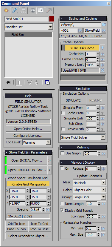
Stoke Field Sim Parameters Rollout
This rollout contains the main controls of the object, including access to the Magma Editors and the settings of the World Space Grid.
Open INITIAL Flow… / Open SIMULATION Flow… buttons
- Pressing these buttons will open the Magma Editor where you can define either the Initial Fields or the Simulation logic using all available operators and input nodes.
- The Stoke Field Simulator Editors expose an additional “Stoke” operators category containing nodes specific to the product.
- The color indicator to the left of the buttons will be green when the respective Magma flow is valid, and red when the Magma flow has reported an error during simulation. It will NOT be updated when setting the flow in the Editor unless the SIMULATE… button is pressed!
[>] Preset Flows buttons
- Pressing these buttons will show menus providing an option to explore the respectrive default Stoke Field Simulation Initial or Simulation flows save directories, plus a list of all flows saved in these directories.
- Selecting a pre-saved flow from the list will automatically load it into the Magma Editor without opening it. This can be used to quickly switch the fields to various presets.
>Enable Grid Manipulator checkbutton
- This checkbutton is a shortcut to the Select And Manipulate feature of 3ds Max.
- When a Stoke Field Simulator object is created, this system feature will be activated automatically to allow the interactive resizing of the grid directly in the viewports by dragging the sphere handles at the 6 sides of the bounding box.
- Note that changing this option will update the 3ds Max Main toolbar, but changing the toolbar icon’s state will not update the Field Simulator’s checkbutton in the Command Panel unless you reselect the object manually. In the latter case, the states of the system icon and the object’s checkbox could get temporarily out of sync.
- The Grid Manipulator lets you resize each side individually by dragging the respective handle, resize both sizes symmatrically relative to the location of the object icon by holding down the SHIFT key while dragging, or resize all 6 sizes symmetrically relative to the object icon by holding down both SHIFT and CTRL keys while dragging.
X, Y and Z World Space Grid Size spinners
- The 6 value spinners define the Minimum and Maximum extents of the Field’s Grid in World Space.
- The left column represents the Minimum values, the right column represents the Maximum values.
- The Min. and Max. values will “bump” each-other to ensure the Minimum is always below the Maximum by about two Voxel Spacing sizes. For example, if the Spacing value is 3.0, the Min. X is -50.0 and the Max.X is 50.0 and you enter 60.0 for Min.X, the Max.X will be automatically bumped up to 66.0. When using the Manipulator handles though, the Min.X will stop about two voxel sizes before the Max. X and won’t bump it up.
- NOTE that the value spinners are in absolute world-space world units and are NOT directly affected by the transformations of the object icon! (except when using the symmetrical options of the Grid Manipulator described above, or aligning to the icon explicitly using the buttons mentioned later on this page)
- The Field Grid will always be aligned to the world coordinate system and cannot be rotated or scaled. This was a conscious design decision to simplify the data flow inside Magma.
Spacing spinner
- The Spacing spinner defines the Grid spacing of the Field Simulator object.
- The Spacing is used in several cases
- When displaying samples in the viewports, the Spacing will define the highest resolution to display (unless Reduction is performed automatically or manually to draw only every Nth row).
- When performing the simulation, the Grid Spacing will provide the voxel size for the Fluid Solver (if any), as well as the default grid spacing of all grid-based operators unless overridden explicitly by the operator itself.
- The Spacing and Grid Size will be passed up the stack and will provide the default values for any relevant Field Modifiers like the SimpleFluid modifier, unless the Spacing is overridden explicitly in the modifier itself.
Grid Voxel Counts text field
- This text field displays the X, Y and Z voxel count of the current grid, as well as the total number of voxels in the grid based on the Size and Spacing values.
- The text field is not editable, but its text can be copied to be pasted elsewhere.
Grid To Icon button
- Pressing this button will center the Grid to the current icon position while ignoring its rotation and scale transforms.
- This feature can be used to move an existing Grid to a new location in world space without changing its size - simply move the icon first, then press the button to move the Grid to it.
Base To Icon button
- Pressing this button will center the Base (XY) of the Grid to the current icon position while ignoring its rotation and scale transforms.
- This feature can be used to move an existing Grid to a new location in world space without changing its size. Since the default creation mode of the Field Simulator object is to have its base centered at the icon, this option lets you relocate the grid by moving the icon first, then moving the existing Grid to it without centering along the Z axis.
Icon To Grid button
- Pressing this button will center the icon to the World Space Grid’s position.
- This is the reverse operation of the Grid To Icon button.
Icon To Base button
- Pressing this button will center the icon to the World Space Grid’s Base (XY) position.
- This is the reverse operation of the Base To Icon button.
- NOTE that you can combine these buttons to move the grid by half Z size up or down. For example pressing Icon To Base and Grid To Icon will move the grid half a height down, pressing Icon To Grid and Grid To Base will move half a height up. Repeatedly pressing these combinations can shift the grid multiples of the half height up or down…
Select Dependent Object… button
- Pressing this button will display a menu with Objects that use this Stoke Field Magma object as input, for example Stoke Particle Simulator, Stoke Field Force, Stoke Field Follow PFlow Operator, any object with a Material containing a Stoke Field Texmap etc.
- If no dependent objects have been found, the list will display one item stating that.
- Note that all objects exposing a pick button for a Field input provide a [>] button with the option to “Select Field Source”, thus allowing you in turn to select the Stoke Field Magma if it was picked.
Saving And Caching Rollout
Save Path controls
- The edit text field shows the base save path where the Stoke Field Simulator will save VDB files.
- By default, the path will be set in the user’s local data folders via a $default symbolic pathname. It resolves to C:Users[YOURUSERNAME]AppDataLocalThinkboxStokeFieldCache
- Each Stoke Field Simulator object will generate a unique random ID upon creation. This ID will be used to create a sub-folder called StokeField_XXXX_YYYY within the base path.
Folder button
- Left or Right-clicking the button on the right side of the Save Path will open a menu with the options to
- Open a directory browser to pick a different base path;
- Save the currently specified path as default for future Stoke objects;
- Reset the base path to the last stored default value;
- Open the Windows Explorer at the output path.
Version field
- This field defines the sub-folder within the <BasePath>StokeField_XXXX_YYYYpath in which to store the Stoke Field Simulator’s disk cache.
- If no folders exist in the base folder yet, the default name will be “v001”.
- If folders exist in the base folder, each new Stoke Field Simulator object will create a version folder with one higher than the last number found in the sub-folders names. For example, if there are folders called “v001”, “tk102” and “bobo234”, the next folder created will be “v235” because “234” is the largest number found in any of the sub-folders.
- You can enter ANY valid folder name instead of a version string, for example “test”, “temp” and “deleteme” are all valid names even though they contain no numbers.
- You can enter an existing sub-folder name - this will set your Stoke Field Simulator object to use that folder and will potentially connect the Memory Cache to the existing Disk Cache.
Version Presets button
- Clicking the [>>] button next to the Version field will open a menu with the options to
- Create a New Folder - a new version folder with the next available number will be created.
- Set an existing folder as the current Disk Cache
File Name Prefix field
- The second field next to the version folder defines the file prefix to save to.
- The default name is “StokeField”, and it will produce VDB files named “StokeField_0000.vdb” etc.
- You can enter any name prefix to produce a new sequence within the current version folder.
Cache Options group of controls
Save Indicator
- The color swatch to the left of the >Save Disk Cache button indicates whether there are VDB files pending to be written by the background thread.
- When it is red, VDB files are still being written from the pending memory buffer to disk.
- When it is green, all files have been written to disk.
- When it is gray, no simulation data has been found in the Stoke object.
>Save Disk Cache checkbutton
- When checked, the Disk Cache will be used and VDB files will be saved by asynchronous background threads during and after the simulation.
- When unchecked, no saving will be performed and all simulation data will be cached in the Memory Cache only.
[+] button
- Pressing this button will create a new Stoke Field Loader, set to load the Disk Cache saved by the current Stoke Field Simulator object.
- If any frames are still pending, they will be saved first (in other words, a Cache Flush will be performed first which can take a while depending on the size of the simulation.
Cache Nth value spinner
- Default is 1.
- When set to 1, every frame in the specified Memory Cache range (or Simulation range) will be stored in memory.
- When set to a value above 1, only every Nth frame will be cached in memory, and all intermediate frames will be interpolated from their neighbors - see Retiming and Use Playback Interpolation for more details.
Memory Limit spinner
- This value defines the Memory Cache limit in Megabytes.
- The Memory Cache Limit is used to cap the memory usage of the Stoke Field Simulator object.
- The Limit will be shared by the Memory Cache and the Pending Saving Buffer automatically.
- During simulation, the majority of the Limit will be allocated to the Pending Buffer. Once the data is cached to disk, the memory will be passed back to the Memory Cache for faster playback.
Used Memory field
- This text field shows the memory usage of the Memory Cache and the Pending Buffer.
[X] button
- Pressing this button will open a context menu with the following options:
- RESET the Memory Cache. This option will clear the Memory Cache and all unsaved simulation data will be lost. It will not affect the Disk Cache, so if VDBs were written to disk, they will be preserved. If the background was still saving VDBs, the current file will be saved and the rest will be skipped.
- FLUSH the Memory Cache - Save to Current Cache Path. This option will force any unsaved simulation data to be written to disk. This will happen in the Main Thread and NOT in the background, so it might lock the computer for a long time.
- Save the Cache to a NEW VDB Sequence. This will force the resaving of all existing data to a new file sequence at a user-defined path. This will happen in the Main Thread and NOT in the background, so it might lock the computer for a long time.
Cache Usage Graph
- The graph shows the content of the Stoke Memory and Disk Caches using one pixel wide bars to represent each frame of the simulation.
- The graph is 150 pixels, thus showing 150 frames in a row.
- If more than 150 frames were simulated, multiple rows will be used.
- Each 10th frame will be drawn slightly darker to produce a reference grid.
- The current frame will be drawn slightly lighter.
- Gray color means “unused”
- Red color means “data missing”. This is the case for example if a simulation was canceled prematurely (see the screenshot), or if simulating with Every Nth frame (in-between frames will be shown in red).
- Blue color means “exists on disk, but not in memory”. These are frames that have been written to disk, but have been unloaded from the Memory Cache. They can be loaded if the respective frame is requested by the scene time.
- Green color means “loaded in memory”. These are frames that have either been saved to disk and are also in memory, or are in memory and still not saved to disk.
- If the Memory Limit is set relatively low or the particle count is very high, dragging the time slider will cause the graph to display portions of green and blue changing to show dropping of frames from memory (green becoming blue), and disk data being loaded into memory on demand (blue becoming green).
Simulation Rollout
SIMULATE button
- Pressing this button will perform the field simulation according to all other settings described here.
- A STOP button and a progress bar will appear - pressing the button will stop the simulation prematurely.
RESUME button
- Pressing the RESUME button will continue the simulation.
- It is initually grayed out.
- It will become available if the simulation has been stopped prematurely, or if the Simulate Until spinner is set to a higher value than the last simulated frame.
- It will be disabled if any relevant simulation settings including the distribution and velocity field objects are changed. Changing the values back to their last settings during the simulation will reenable the button.
- The Cache options (Memory Limit, Cache Nth) can be changed before resuming.
Simulate From value spinner
- This value defines the start of the simulation range.
Cache From checkbox and value spinner
- The checkbox is unchecked by default.
- When checked, the simulation will start on the frame defined by Simulate From value, but no caching will be performed before the Cache From frame.
- This allows for Pre-rolling the simulation and saving only the frames that matter.
Simulate Until value spinner
- This value defines the end of the simulation range, and implicitly also the end of the caching / saving interval.
Sub-Steps value spinner
- This value defines the number of sub-steps within a single frame.
- The default value is 1, producing one step per frame.
- Increasing the value will perform multiple sub-steps within the frame interval, potentially capturing finer details
- This is especially useful when using fast-moving particles as Velocity Field that can jump over voxels within a frame.
- Note that increasing the Sub-Step value will increase the simulation time proportionally.
Preview Nth checkbox and value spinner
- When the checkbox is checked, the viewport will be updated during simulation.
- The value spinner defines the Nth frame to update if the checkbox is checked.
- Default is 5, update on every 5th frame.
- Setting the value to 1 will update each frame during simulation, resulting is some overhead.
Fluid Solver drop-down list
- By default, the list will be set to “Simple Fluid Solver” which performs advection using an FFT solver and automatically removes divergence from the Velocity field.
- The other option is “No Fluid Solver”.
- More options might be added in the future to implement more advanced fluid solvers.
Retiming Rollout
Use Graph checkbox
- This option toggles the retiming of the Stoke Fields on and off.
- When unchecked, the current time (scene time slider, render time) will control the frame to be played back.
- When checked, the value of the Graph spinner at the current time will be used to determine the frame to be played back.
Graph value spinner
- This value defines the frame to be played back / rendered when the Use Graph checkbox is checked.
- When not animated, the value will cause the specified frame to be played back on every frame.
- When keyframed, the animation graph will drive the playback, allowing for free retiming including playing backwards, speeding up, slowing down etc.
Viewport Display Rollout
The Viewport Display rollout contains the controls related to the visualization of the Field Simulator data in the viewports.
On checkbox
- When checked (default), the simulated fields will be sampled according to the Grid Spacing and Size values and represented in the viewports according to the settings of the other controls in the rollout.
- When unchecked, no samples will be drawn regardless of the other relevant controls’ values.
Reduce value spinner
- The Reduce value spinner defaults to 0.
- When set to 0, the Field Simulator’s grid will draw all samples in the viewports, unless Auto-Reduce has kicked in to preserve reasonable performance.
- When set to a value higher than 0, and if Auto-Reduce has not enforced a higher reduction value, only every Nth sample will be drawn along each of the 3 axes.
Update Channels button
- Pressing this button will reevaluate the Fields defined in the Magma flows and repopulate the drop-down lists below with the currently available channels.
- This is useful when modifying the Output nodes in the Magma flows and attempring to use the new channels to control the viewport display.
Mask drop-down list
- This list provides the options “No Mask” as well as any Scalar Fields defined in the Magma flows.
- By default, a Density field is defined in a new Field Simulator object, and the Density channel will be selected automatically.
- The Mask channel is used to determine where to display viewport samples.
- Samples (Dots or Vectors, depending on the Display list below) will only be drawn where the Mask channel has a positive value.
- When set to “No Mask”, no Dots will be drawn when Display is set to “Large Dots”, and all Vectors will be drawn when Display is set to a Vector channel.
Color drop-down list
- This list provides the options “Object Color” (default), as well as any Vector fields defined in the Magma flow.
- When “Object Color” is selected, the samples (Dots or Vectors) drawn in the viewports will use the object color of the Field Simulator - either the wireframe color, or the Material color, if a material is assigned.
- When a Vector field is selected, the channel’s values will be used to colorize the samples.
Display drop-down list
- This list provides the options “Large Dots” (default), as well as any Vector fields defined in the Magma flows.
- When “Large Dots” is selected, the samples will be drawn as dots in the viewports.
- When a Vector field is selected, the samples will be drawn as lines in the viewport according to the direction and magnitude of the field at the sample point, unless overridden by the controls below.
Norm. Length checkbox
- When unchecked, the Vector display will draw the samples as lines with length equal to the Magnitude acquired from the field, multiplied by the Scale value.
- When checked, the Vector Magnitude will be normalized to length of 1.0, then scaled by the Scale value before displaying.
Scale value (unlableled, to the right of the Norm.Length checkbox)
- Defaults to 1.0 and is used to scale the Vector magnitude of Vector Display samples in the viewports as described above.
- Note that Velocity fields are stored as World Units Per Second, so the Vector Display will draw lines that are N times longer than the per-frame velocity where N is equal to the FPS settings. Thus, at 30 fps, you need to use 1.0/30.0=0.03333 Scale to display Vectors with Magnitude in World Units Per Frame!
Display Grid Bounds checkbox
- When checked, the Grid Bounds will be drawn in the wireframe color of the object in the viewports.
- When unchecked, the Grid Bounds will not be drawn in the viewports.
- The Grid Bounds bounding box can be used to select the object instead of clicking on the Icon or the Samples.
Icon Size value spinner
- The Icon Size defaults to 30.0 units and controls the display size of the object’s icon.
- There is no option to disable the Icon display to ensure the object is always easily selectable even if the On and Display Grid Bounds options are unchecked.
- The Icon Size can be set to 0.0 though if absolutely necessary to “hide” the icon.
Manipulator Handles Min. Size and Max. Size value spinners
- The Min.Size and Max.Size value spinners will clamp the size of the Grid Size Manipulator Handles (green spheres on the 6 sides of the Grid).
- Normally, the Handles will change size according to the size of the Grid, so larger Grids would provide larger handles to retain visibility and usability when zooming out a lot, while smaller Grids would provide smaller handles.
- Use these controls to adjust the size of the handles to avoid extremely small or extremely large display.
Object Creation Workflow
The Stoke Field Simulator object can be created using several methods:
Using A MacroScript On A Toolbar or Keyboard Shortcut
- Alternatively, you can customize the 3ds Max UI to place the same MacroScript used by the Stoke menu on a toolbar, QuadMenu or assign to a dedicated Keyboard Shortcut.
- Simply use the Main Menu > Customize > Customize User Interface dialog to locate the “Stoke” category and assign the MacroScript as needed.
- The actual creation procedure will be identical to the one described in the Stoke Menu section above.
Using the 3ds Max Create Tab in the Command Panel
You can also use the regular 3ds Max workflow for object creation which is similar, but slightly different from the Stoke Menu / MacroScript approach.
- Activate the Create tab of the 3ds Max Command Panel
- Make sure you are in Geometry mode.
- Select “Stoke” from the Category drop-down list
- Click the “Field Sim” button to enter creation mode
- Click in the viewport to define the one corner of the Grid’s Base, then hold the Left Mouse Button and move the mouse to define the second corner.
- Release the Left Mouse Button to set the Base and move the mouse to define the height.
- Click the Left Mouse Button a second time to set the height and finish the current object’s creation.
- Note that 3ds Max will remain in Field Sim object creation mode and you can start creating another object immediately, or Right-Click to exit creation mode.
- Right-clicking at any point during the object creation steps outlined above will cancel the creation of the object AND delete any unfinished object (compare to the MacroScript workflow above where this is not the case).
Using MAXScript
You can create a Stoke Field Simulator object by executing the following code:
StokeFieldSIM()
The resulting object will have a Spacing of 2.0 and Grid Size of -2/2, -2/2, 0/4 unless specified explicitly via creation parameters.