Velocity Field From Mesh Tangents
Applicable to Stoke MX 2, Last Edited December 8, 2013
Overview
The following tutorial discusses the creation of custom Velocity Fields from surface tangents of a Torus primitive using the Field Magma object introduced in Stoke MX 2.
The Base Scene
- Start a new 3ds Max scene.
- Create a Torus primitive with Radius 1 of 40.0, Radius 2 of 15.0, Segments and Sides set to 32. The actual location of the Torus does not matter, but let’s create it at the world origin for convenience.
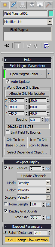
- With the Torus selected, hold the SHIFT key and select the menu item “Create a Field Magma object…” from the Stoke menu. The grid size will be set to match the size and location of the Torus.

- Uncheck the “Limit Field To Bounds” checkbox to affect any particles regardless of their location - inside or outside the grid.
- Switch the Viewport Display mode from “Large Dots” to “Velocity”.
- Switch the Viewport Color mode from “Object Color” to “Velocity”.
The Basic Magma Flow
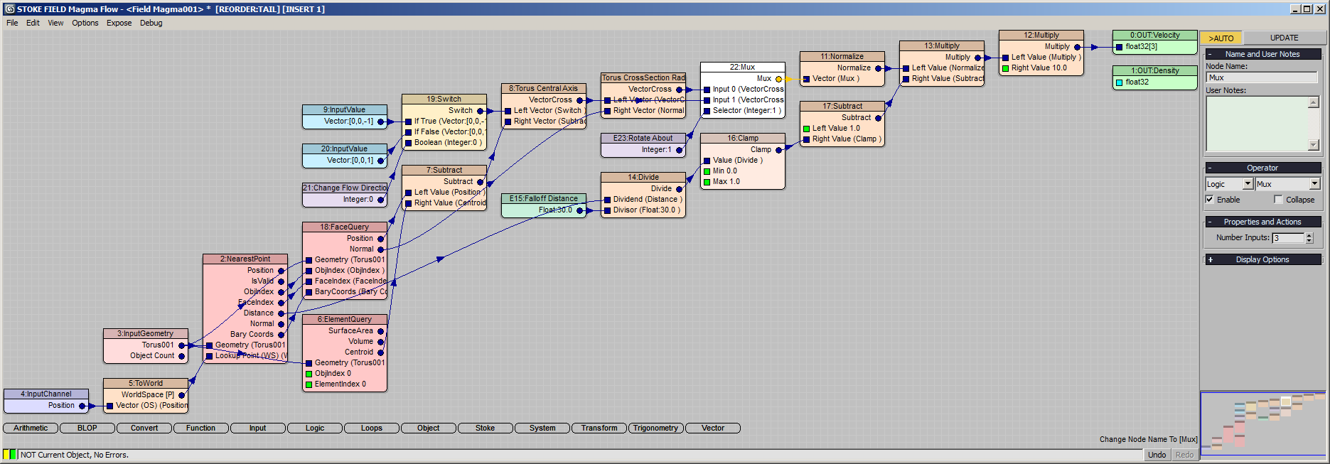
We will be generating a Velocity field, so we will be writing to the existing Velocity Output node.
- Select the existing Velocity Output node.
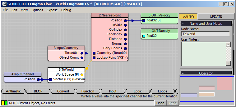
- Press the O key to show the Object category menu, then press N for NearestPoint. Its Position output will be connected automatically to the Velocity Output.
- Drag a connection from the first socket of the new node and release over an empty area of the Editor to create an InputGeometry node.
- In the new InputGeometry node, pick the Torus as the only source mesh.
- Drag a connection from the second input socket of the NearestPoint operator and release over an empty area of the Editor to create an InputChannel Position node. Note that in Stoke, the Position is already in World Space and does not require an explicit conversion. In Krakatoa Magma and Genome, the same operation would also create a ToWorld conversion operator.
- Press CTRL+R to enable the Auto-Reorder mode.
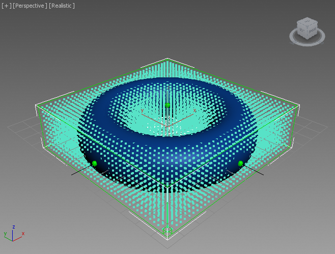
RESULT: At this point, the viewport will display Velocity vectors pointing radially outwards, because we are feeding into the Velocity Output the world-space positions of the nearest points.
- Drag a connection from the output socket of the InputGeometry node and release over an empty area, then select Object > ElementQuery from the menu.
- Select the NearestPoint operator again and press the - key on the Numeric Keypad to create and insert a Subtract operator between the Position output socket and the Output node.
- Connect the Centroid (3rd output socket) of the ElementQuery node to the second input socket of the Subtract operator. This will define a vector connecting the center of the Torus with the nearest point on the surface found by the current sampling position.
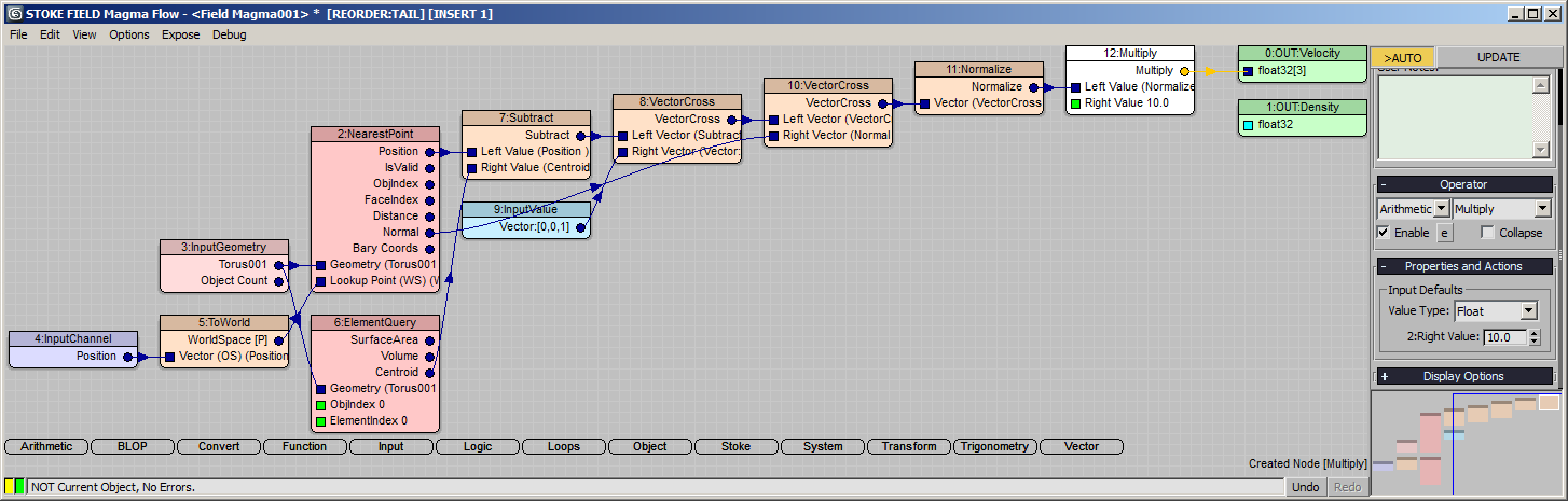
- Select the Subtract operator and press the , (comma) key to create and connect a VectorCross operator.
- Press SHIFT+3 to connect a [0,0,1] Vector InputValue to the VectorCross. This will calculate the vector cross product of the up vector and the previously calculated center-to-surface vector.
- Select the VectorCross again and press the , comma key once more to add another VectorCross.
- Connect the Normal output of the NearestPoint to the second socket (Right Vector) of the second VectorCross. The result will be the Tangent to the surface at the nearest point!
- Press V for Vector category and then N for Normalize to make the length of the Tanget equal to 1.0.
- Press the * key on the Numeric keypad to add a Multiply node to scale the length of the Tangent. Enter 10.0 for the Right Value.
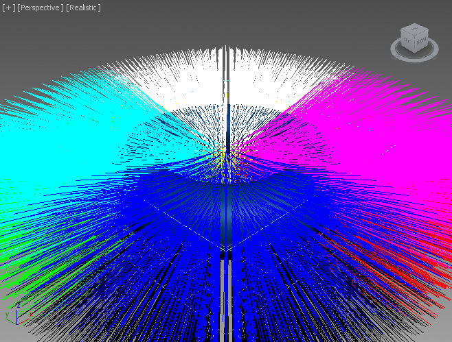
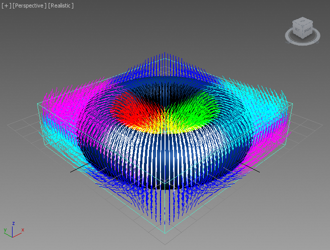
RESULT: At this point, we have a velocity field consisting of vectors tangential to the Torus’ surface (left image).
To see the samples better, select the Field Magma object and change the Spacing parameter to 6.0 to produce less samples (right image).
Falloff By Distance
Next, we will scale the Tangential Velocity field based on the distance from the surface.
- Select the Normalize node and press the * key on the on the Numeric keypad to insert another Multiply operator.
- Connect the Distance output of the NearestPoint to the second socket of the Multiply operator.
- Click the new connection to select it, then press the / key on the Numeric keypad to insert a Divide operator.
- Press Ctrl+1 to connect a Float InputValue node, then enter 20.0 as the falloff value.
- Select the new Divide operator and press F for Function and then C for Clamp - this will clamp the result between 0.0 and 1.0.
- Right now we have a value of 0.0 at and inside the surface (because Distance inside the volume is negative and clamped to 0.0) and 1.0 at 20.0 units from the surface on the outside, so we need to invert the value by subtracting from 1.0. Simply press the - key on the Numeric Keypad, then press CTRL+W to swap the first two input sockets to produce Subtract from 1.0!
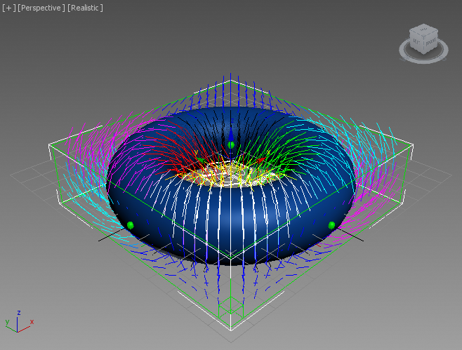
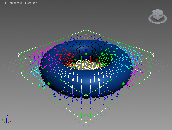
RESULT: At this point, the Velocity Field will have the correct falloff, but it might not be obvious (left image).
You can change the World Space Grid Size X and Y of the Field Magma from -55/55 to -80/80, and the Z values from -15/15 to -40/40 to see more samples and witness the falloff as drawn by the Velocity lines (right image):
Driving A Stoke Particle Simulation
In the next step, we will apply the Velocity field to the particles of a Stoke object.
- Go to the Create tab of the Command Panel of 3ds Max
- Click on the Box primitive button and expand the rollout “Keyboard Entry”
- Enter X:0.0 Y:0.0 Z:-40.0, Length:160.0 Width:160.0 Height 80.0
- Click the Create button - this will create a Box around the Field Magma’s Grid Bounding Box.
- Press F3 to switch the viewport to Wireframe.
- Change the scene Time Range to 0 to 200.
- Select both the Box and the Field Magma objects in the viewport.
- Click the “Create a Stoke Particle Simulation…” menu item from the Stoke menu, then click in the viewport to define the location of the icon.
RESULT: The Box001 object will be added as Distribution Source, the Field Magma will become automatically a Velocity source in the newly created Stoke object.
- In the Simulation > Particle Birth group of controls, check “Emit Until” and enter 0.
- In the Rate/Frame field, enter 10000.
- In the Distribution Sources tollout, select the Box001 entry and switch the drop-down list from Surface to Volume - this will emit particles inside the Box instead of using only its faces.
- In the Viewport Display rollout, switch the Display drop-down list from Large Dots to Velocity.
- Enter 30.0 in the value field to the right of the Norm.Length option (the checkbox should remain unchecked).
- In the Simulate rollout, check the Preview Nth checkbox and leave it at the default value of 5.
- Press the SIMULATE button to start the simulation.
RESULT: As the simulation progresses, you should see the particles within the falloff radius swirling around the Torus as expected.
- Select the Field Magma and disable the On checkbox under the Viewport Display rollout to hide the Field lines and speed up the viewport display.
- Play back the resulting animation:
Improving The Motion
As you might notice from the resulting animation, the particles are not moving smootly around the surface. The cause for this jittering is that we are currently using the Face Normals acquired by the NearestPoint operator.
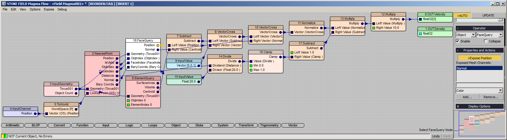
We could acquire the Smoothed Surface Normals instead to produce better motion:
- Open again the Magma Editor of the Field Magma object.
- Select the NeatestPoint operator and click the “Add Face Query” button under the “Properties and Actions” rollout of the Magma command panel - this will insert a new FaceQuery and connect it to all necessary nodes and sockets. Since the default output of the FaceQuery is Position, the flow will remain valid!
- In the “Properties and Actions” rollout of the FaceQuery operator, click on the list of typical mesh channels (showing Color as top choice) and scroll down to select the Normal entry, then click the Add… button - a new Normal output socket will appear in the FaceQuery node.
- Drag a connection from the new Normal output socket to the Right Vector second input socket of the second VectorCross operator (currently connected to the Normal output of the NearestPoint).
- Select the Stoke particle simulation object and press SIMULATE again to recalculate using the new vector field.
RESULT: The motion is now smooth because the Tangents are calculated using the smoothed surface Normals.
Changing The Direction Of The Flow
Currently, the particles are moving around the surface in one direction - they rise up on the outside and dive down on the inside. It would be very easy to flip the direction once, but we will actually expose a checkbox in the User Interface of the Field Magma object to do so.
- Select the Field Magma object and check the On checkbox under Viewport Display to enable the display of the field.
- Open the Magma Editor of the Field Magma object.
- Select the first VectorCross operator (the one that has the InputValue Vector [0,0,1] as input) and press CTRL+W. This will swap the input sockets and the direction of the velocity field will be flipped!
- The alternative to flip the direction would be to invert the direction of InputValue Vector to [0,0,-1] - select the InputValue Vector [0,0,1] and change it to [0,0,-1]. The direction of the flow will be flipped back again!
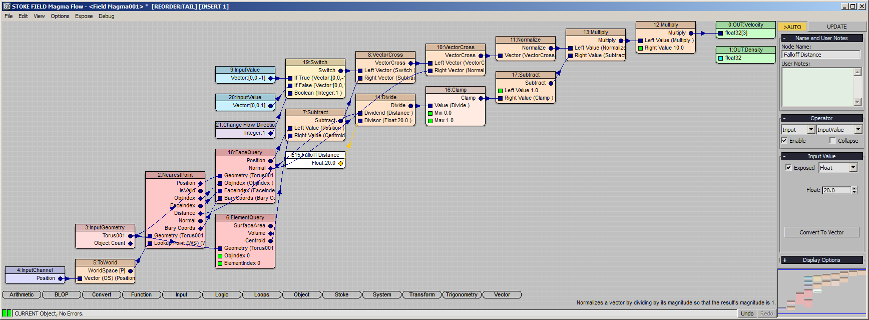
- We can use this to pass a flipped vector based on a Logic > Switch operator. With the InputValue node selected, press the / key at the bottom row of the keyboard (the one with the ? character) to insert a Switch operator. Alternatively, you can press L and then W to do the same. The InputValue [0,0,-1] will now be the first (If True) input of the Switch.
- With the Switch node still selected, press SHIFT+3 on the top keyboard row to create and connect a new InputValue Vector [0,0,1] to the second (If False) socket of the Switch.
- Now press 1 on the top keyboard row to create and connect an InputValue of type Integer with a value of 1 (equivalent to a True value).
- In the Magma Editor command panel, enter “Change Flow Direction” as the Node Name under “Name and User Notes” rollout.
- Check the “Exposed” checkbox in the Magma Editor command panel to expose the Integer value. When an Integer InputValue node is connected to the third socket of a Switch operator, it automatically becomes a checkbutton when exposed!
- Select the Float InputValue with value of 20.0 defining the falloff range and rename it to “Falloff Distance”, then check its “Exposed” checkbox.
RESULT: We now have both a value spinner and a checkbutton under “Exposed Parameters” in the 3ds Max Command Panel of the Field Magma. Toggling the checkbutton will flip the flow direction, and changing the Fallof Distance will adjust the influence of the surface.
- In the “Exposed Parameters” rollout of the Field Magma, uncheck the “Change Flow Direction” checkbox.
- Select the Stoke particle simulation object and hit SIMULATE again.
RESULT: The particles are now moving in the opposite direction, rising from the inside and dropping on the outside:
Switching The Axis Of Rotation
So far, we have been rotating about the shorter Radius 2 of the Torus. Let’s add an option to rotate about the central axis (Radius 1), which is the other surface Tangent we calculate already using the first VectorCross operator!
- Open the Magma Editor, select the second VectorCross operator and press CTRL+P to disable it (pass through the data) - if you enable the display in the viewport, you will see that the Velocity Field is now following the other radius of the Torus!
- Press CTRL+P again to toggle the first VectorCross operator back on.
- Press L for Logic and M for Mux operator - it will be inserted behind the first VectorCross operator.
- Drag a connection from the output socket of the first VectorCross to the second input socket of the Mux operator.
- Press 1 to connect an InputValue Integer with value of 1 to the third input socket of the Mux operator.
- Rename the InputValue control node to “Rotate About” and check the “Exposed” checkbox.
- Rename the first VectorCross node to “Torus Central Axis”.
- Rename the second VectorCross node to “Torus CrossSection”.
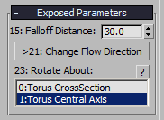
RESULT: The InputValue node controlling which input of the Mux operator to use will be exposed as a ListBox with name based on the name of the InputValue node, and entries based on the names of the nodes connected to the first two inputs!
- Change the Falloff Distance exposed control to 30.0 to move more particles.
- Select the Stoke particle simulator.
- Click on the [>>] button next to the version field under “Saving and Caching” and select “New Version” - the value will be changed to v002.
- Press the SIMULATE button again to simulate using the new Velocity Field direction.
- Once finished, play back the simulation - the particles will now move following the central axis of the Torus:
Additional Notes
Particles Inside The Volume
You could further expand this setup to handle particles inside the volume of the Torus differently.
Currently, particles inside the volume produce a negative Distance. Since we are clamping between 0.0 and 1.0 and subtracting from 1.0, all particles inside the volume have no falloff and are moving at maximum speed.
You could add a Switch with a Less Than 0.0 test and send 0.0 as the Multiplier to set the velocities inside the volume to 0.0, or insert an Arithmetic > Abs operator after the Distance to produce the same falloff inside the volume as outside.
Animating The Torus
Since we have allowed calculations anywhere in space by unchecking the Limit To Bounds option, you can freely animate the Torus’ position in space or change its radii to produce changing fields over time. The Grid size only controls the visualization in the viewport at this time, and you have to make sure there are particles where the Torus is going, but otherwise feel free to animate the setup and see what results it could produce. You could for example use it as an additional velocity or force field to produce swirling motion in otherwise linearly moving particles, e.g. in a mushroom-like explosion.
The above setup does not support changing the rotation of the Torus though - it would require getting its Z axis as the up vector to calculate correct tangents if it is tilted in space.
Using Other Meshes Than Torus
This setup applies mainly to a Torus and won’t work well with objects like Sphere or Teapot for example. The current setup uses the fact that the Torus has only one element in the mesh, and a hole in the middle, so there is never a situation where the cross product of the vectors cannot be calculated because of a vector parallel to the Up Vector 0,0,1. Replacing the Torus with a Sphere will cause all particles to gather around one of the sphere’s poles (depending on the direction) as there is no route to move back down, and the poles produce parallel vectors in the first VectorCross calculation!