Stoke Field Controlling Particle Flow
Applicable to Stoke MX 2, Last Edited May 22, 2014
Overview
As we already saw in the very first tutorial, Stoke MX 2 provides a dedicated Stoke Field Follow Particle Flow operator which can transfer field data into the particle simulation. In the following tutorial, we will explore some of the operator’s capabilities to set channels and even control the logic of a Particle Flow simulation.
The Base Scene
Let’s create a simple Noise-based Velocity Field to drive our Particle Flow.
Creating The Magma Field
- Start a new 3ds Max scene.
- Change the Time Range End to 200
- Open the Stoke menu, hold SHIFT and select “Create a Field MAGMA object …” - this will create a default grid with a size of about 100 units at the world origin.
- Click the “Open Magma Editor…” button.
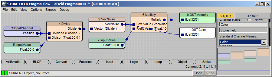
- Select the Velocity Output node and press F for Functions and V for VecNoise - a Log Window might pop up telling you there are unconnected nodes. You can minimize it, or suppress further messages by expanding the “Help” rollout of the Field Magma object and switching the Log Level list to “None”.
- In the Magma Editor, with the VecNoise selected, press SHIFT+P to create a Position InputChannel. Now the Noise is based on the position of the current sample.
- With the Position InputChannel still selected, press the / key on the Numeric Keypad to insert a Divide operator.
- Press CTRL+1 to connect a Float InputValue with a value of 1.0 to the second socket of the Divide operator. Then enter 30.00 as the new value. This is the Scale of the Noise - we divide the Position vector, and thus cause the VecNoise to produce larger noise patterns.
- Select the VecNoise operator again and press the * key on the Numeric Keypad to insert a Multiply operator between the VecNoise and the Velocity Output.
- Press CTRL+1 to connect a Float InputValue into the second socket of the Multiply operator. Then enter 100.0 for the value. This will scale the magnitude (length) of the Velocity vectors, producing faster motion in the Velocity field without affecting the directions of the motion.
NOTE: We could have entered the Scale divisor and the Multiplier values directly in the second sockets of the Divide and Multiply nodes. The reason we created two Float InputValue nodes is we want to be able to both keyframe the values and expose them to the Command Panel UI of the Field Magma object if desired. The default values of operator sockets cannot be animated or exposed.
Visualizing The Velocity Field In The Viewport
Let’s show the values we just defined as both colors and lines in the viewport.
- In the 3ds Max Command Panel, with the Field Magma object selected, switch both the “Color” and “Display” drop-down lists in the “Viewport Display” rollout to “Velocity”.
- Since the Velocity is Stoke is expressed in Units Per SECOND but we want to show Units Per FRAME, we have to scale the display. When using FPS of 30, we need to scale by approximately 0.03. Click the [>>] preset button next to the Norm.Length value (checkbox should be unchecked) and select 0.03 from the list. Alternatively, enter the value manually.
RESULT: The Velocity Field is now shown with lines pointing in the direction of motion and having length representing the speed in approximately units per frame.
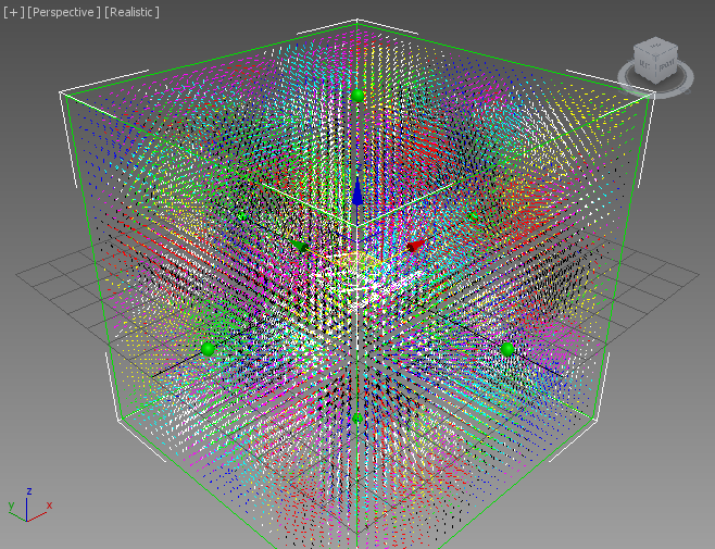
The Color display though is still using the Units Per Second and is quite blown out. We could fix that in the Magma flow:
- Select the Density Output node (which we don’t really need for this tutorial) and switch its channel to Color.
- Connect the output socket of the VecNoise directly to the Color Output, thus bypassing the Multiply node.
- In the 3ds Max Command Panel, press the “Update Channels” button to refresh the lists.
- Select “Color” for the Color display.
- Since the default spacing of the grid is 3.331 and the lines are a bit too short to give us a good idea of the direction of the Velocities, let’s change the Display Scale from 0.03 to 0.1.
RESULT: We can now see a better gradient of colors representing the direction and magnitude of the Velocity field, and a bit longer lines showing us the same data graphically.
Creating The Particle Flow
Now let’s add a Particle Flow to affect with our field.
- Select “Graph Editors” from the 3ds Max Main Menu, then select “Particle View” (or press 6 on the top keyboard row instead).
- Drag a “Standard Flow” into the Particle View.
- Select the “PF Source 001” event and change the “Icon Type” option to “Sphere”, “Diameter” to 30, and “Viewport %” to 100.0.
- Select the Birth operator and change the “Emit Stop” value to 100 and the “Amount” value to 10,000.
- Select the Rotation operator and change the drop-down list to “Speed Space Follow”.
- Select the Shape operator and reduce the “Size” value to 5.0.
- Select the Display operator and switch the “Type” drop-down list to “Geometry”.
- Drag a Stoke Field Force operator from the Depot over the Speed operator and release to replace it.
- Pick the Field Magma from the scene as the “Field Node”. Click in the Particle View to deselect, then reselect the Stoke Field Follow operator to update its display.
- Make sure the Velocity channel source is set to “Velocity” - this is the VecNoise Velocity Field of the Field Magma being read in as the explicit Velocity of the Particle Flow particles.
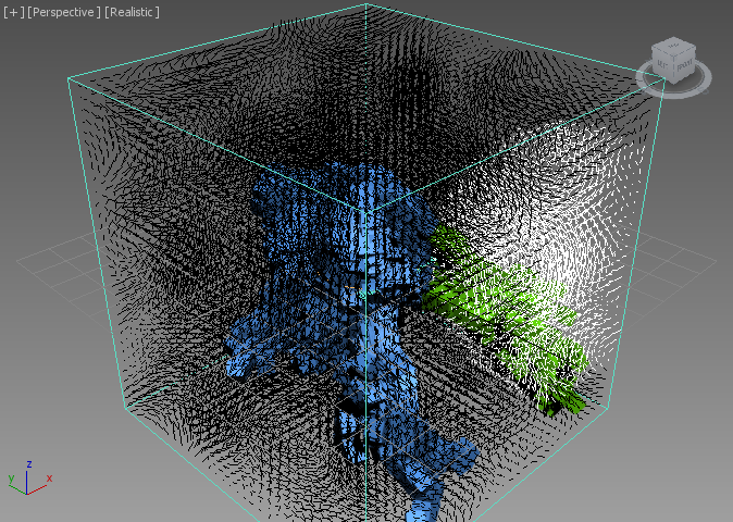
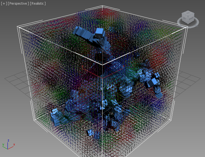
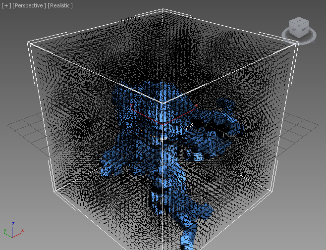
RESULT: If you play back or move the time slider to frame 100, you will see the particles appearing around the origin and then moving around based on the Velocity Field we created.
Limit To Grid Vs. Infinite Field
By default, the Field Magma is limited to evaluating only within the Grid bounds. As we know from a previous tutorial, when the field is fully procedural (in our case the VecNoise function can produce a result anywhere in the world based solely on the Position input channel), we can allow it to be completely unbounded.
Going to frame 200 shows that the particles leaving the Field Grid continue moving straight using their latest Velocity:
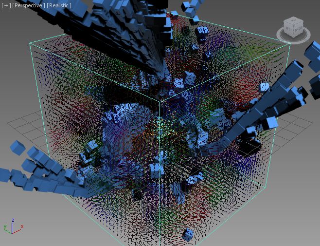
- Select the Field Magma object
- Uncheck the “Limit Field To Bounds” option
RESULT: The particles are now moving according to the VecNoise Velocity Field even outside of the Grid!
Creating Fluid Motion
Currently, the VecNoise produces some random motion in 3D space, but the Field is not “Devergence-Free”. This means that it does not satisfy the requirement for an uncompressibe fluid to ensure that the amount of fluid leaving any point in space is equal to the amount of fluid entering it.
Stoke 2 provides several ways to produce uncompressible fluid by removing the Divergence from a field. All of them require calculations within the Grid Bounds, so the state of the “Limit Field To Bound” option will be ignored.
Note that the Stoke Particle Simulator of Stoke 1.0 performs the same operation internally when “Fluid Motion” is checked for its velocity sources.
Using The Stoke Fluid Motion Modifier
One of the possible approaches for producing fluid motion is the application of a Stoke Field Fluid Motion modifier to the stack of any valid Field object.
- Select the Field Magma object
- Click the Stoke menu in the 3ds Max Main Menu, then select “Add a Field FLUID MOTION Modifier to selected object(s)”
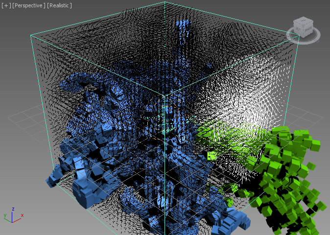
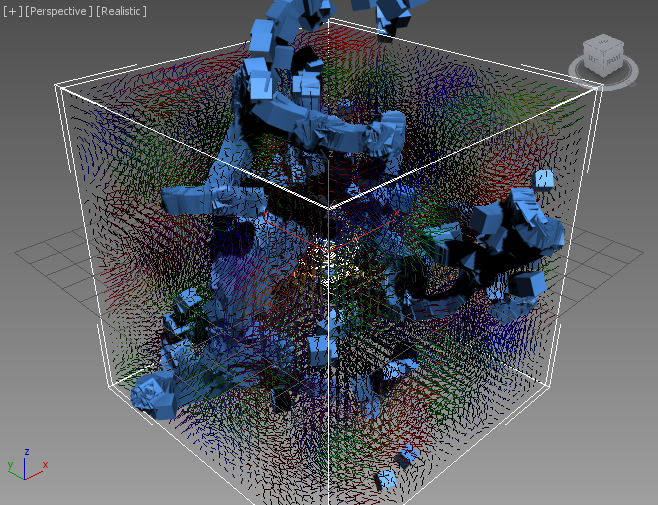
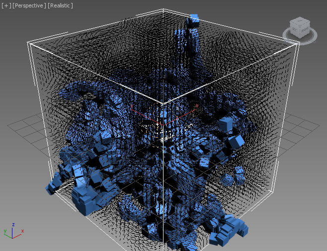
RESULT: A new modifier will be added to the Field Magma object. It defaults to “Velocity” Input Channel and will use the incoming Field’s Grid Spacing value (3.331) unless an explicit Spacing override is requested. The particles will now move differently and will stop at the Grid’s borders because the Velocity outside the Grid would be zero.
Below are Frames 100 and 200 of the new simulation:
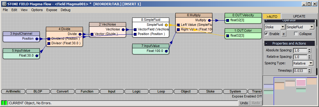
Using The SimpleFluid Magma Operator
Another way to achieve the same result as part of the Magma flow itself is the SimpleFluid operator.
- Select the Field Magma object.
- Delete the Stoke Field Fluid Motion modifier.
- Click the “Open Magma Editor…” button.
- Select the VecNoise operator.
- Press S for Stoke category, then F for SimpleFluid.
- Drag a wire from the second input socket of the SimpleFluid node (Position) and release over an empty area of the Editor - it will connect automatically to the existing Position InputChannel!
RESULT: The particles are now moving exactly like before, but the operation is performed as part of the Magma flow and not on the modifier stack.
Other Available Methods
In addition to these two methods, in some cases you might be using the Stoke Field Simulator object which performs History-Dependent simulation and advection of channels by a Velocity channel. That object exposes a dedicated “Solver” control which offers the “Simple Fluid Solver” option. When simulating using this Solver, the results will also be divergence-free.
Which Method To Use? While these methods produce the same results, they have various benefits and drawbacks.
- The Modifier approach uses the familiar 3ds Max controls on the modifier stack, allowing you to toggle the Fluid Motion option on and off by just turning the modifier on and off.
- The Modifier is also much more obvious to the end user.
- The Modifier can be added to any valid Field Source including Field Magma, Field Simulator, Field Loader etc.
- The Magma Operator approach allows you to apply the calculations at any time within the Magma flow, so it is potentially more flexible.
- The Magma Operator also exposes more controls over the spacing and time step used during calculations, so it can be more powerful.
Note that you can now expose the Enabled state of most Magma operators to the Command Panel of 3ds Max, so turning the Fluid motion on and off is still easily possible without opening the Magma Editor! Let’s see how this is done…
Exposing The Enabled State Of The SimpleFluid Operator
- Select the SimpleFluid operator in the Magma Editor.
- Check the [e] button next to the “Enable” checkbox under the “Operator” rollout.
RESULT: A new checkbutton “>Enable 8: SimpleFluid” will appear in an “Exposed Parameters” rollout in the Modify tab of the 3ds Max Command Panel. Unchecking it will disable the SimpleFluid operator, passing through the VecNoise field without additional processing.
Controlling Particle Flow Logic Using Selection
Particle Flow is Event-Driven. Its logic is based mainly on sending out a particle to other Events whenever a test produces a TRUE result.
The Stoke Field Follow Particle Flow operator supports among other channels the Selected channel of particles, letting you set the Selection state via any Scalar Field in the Field Source object.
In the following test, we will generate a Selection scalar field using Magma by testing against the volume of a mesh. Then we will send out particles that enter the volume of that mesh to another Event by setting their Selected state via that Selection Field and then checking the Selected using the built-in Split Selected test operator.
Creating The Selection Field
- Create a Geosphere primitive with 4 Segments and Radius of 40.0 at world coordinates [40.0, -40.0, 0.0].
- Select the Field Magma and press the “Open Magma Editor…” button.
- Press SHIFT+CTRL+S to create a Selection Output node.
- Press O for Object category, then V for the InVolume operator.
- Drag a wire from the Geometry socket of the InVolume operator and release over an empty area of the Editor to create an InputGeometry node.
- Pick the GeoSphere as the input object.
- Drag a wire from the Lookup Point (WS) socket of the InVolume operator and connect to the existing Position InputChannel node.
- Hide the GeoSphere.
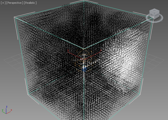
- Change the “Color” drop-down list in the “Viewport Display” rollout of the Field Magma to “Selection”.
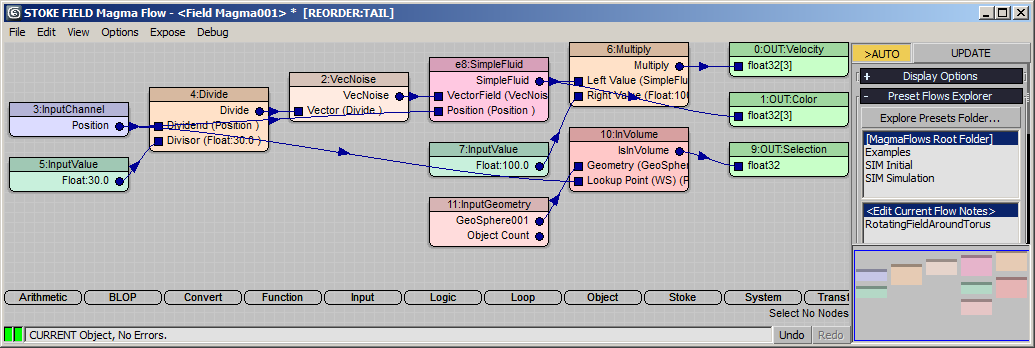
RESULT: At this point, we have a valid Selection Field where points inside the GeoSphere have a value of 1 (TRUE), and points outside have a value of 0 (FALSE). The TRUE samples will be drawn in white, the FALSE will be drawn as black.
Using The Selection To Control Particle Flow
- Open Particle View.
- Select the Stoke Field Follow operator and set “Selected” source to “Selection”.
- Add a Split Selected test after the Stoke Field Follow operator.
- Drag a new Display node to create a new Event, set the color to green and switch the “Selected”list to “Geometry”.
- Connect the output of the Split Selected test to the new Event.
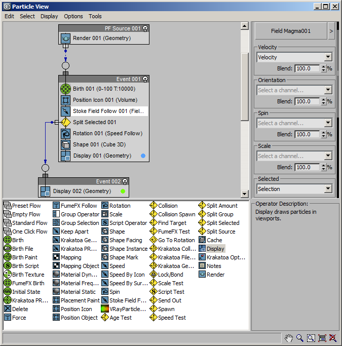
RESULT: Playing back or changing the time will now send out the particles entering the volume of the GeoSphere to the second event, changing their color to green. They will continue moving linearly with the last known velocity because the Stoke Field Follow only applies to the first event.