Deforming A Texture Coordinates Field
Applicable to Stoke MX 2, Last Edited May 20, 2014
Overview
The Stoke Field Simulator will advect every Scalar and Vector field defined in its Magma Flows using the Velocity field.
In the following example, we will initialize a TextureCoord field based on the mapping coordinates of a scene geometry object, then we will advect this field using Velocities from a Particle Flow “raining” over the mesh, and then we will transfer the resulting deformed TextureCoords field back to the mesh using a Genome modifier sampling the Field using the newly introduced InputField Magma operator in Genome.
NOTE that the Genome Modifier ships as an integral part of the Stoke MX 2 package and does not require separate installation!
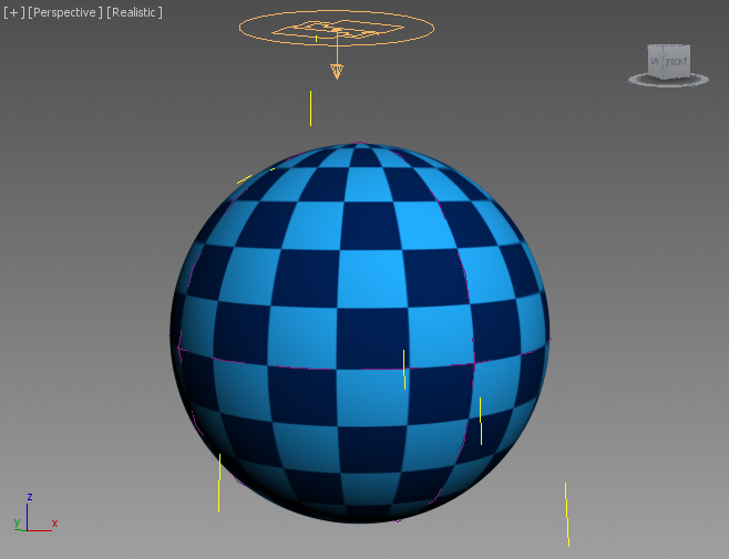
The Base Scene
Our base scene setup will consist of
- A GeoSphere with Radius 20.0, 24 Segments and Mapping Coordinates on.
- A Checker diffuse map assigned to its Standard material to display a regular pattern on the surface to better visualize the result.
- A Particle Flow somewhere above the GeoSphere creating 50 particles over 100 frames that collide with the Sphere using a SDeflector with the same Radius as the GeoSphere.
- The SDeflector will have a high Friction of 97%, and 20% Chaos, with all other parameters set to 0.0, allowing the particles to slide over the surface before detaching at the equator and falling down.
- Default Gravity and a 10% Linear Drag SpaceWarps to control the particles’ acceleration.
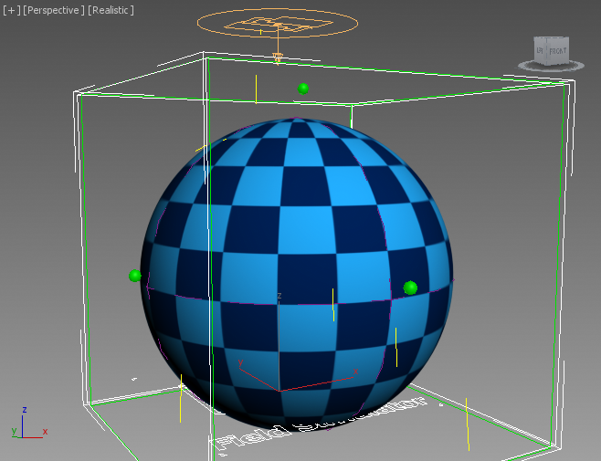
Creating The Field Simulation
- Create a Stoke Field Simulator object and use the Manipulators to set the Grid Size to include the GeoSphere, with enough spacing around it for the particles to also be included.
- Set the Spacing to 1.0 - using higher values will speed up the simulation, but reduce the quality of the result.
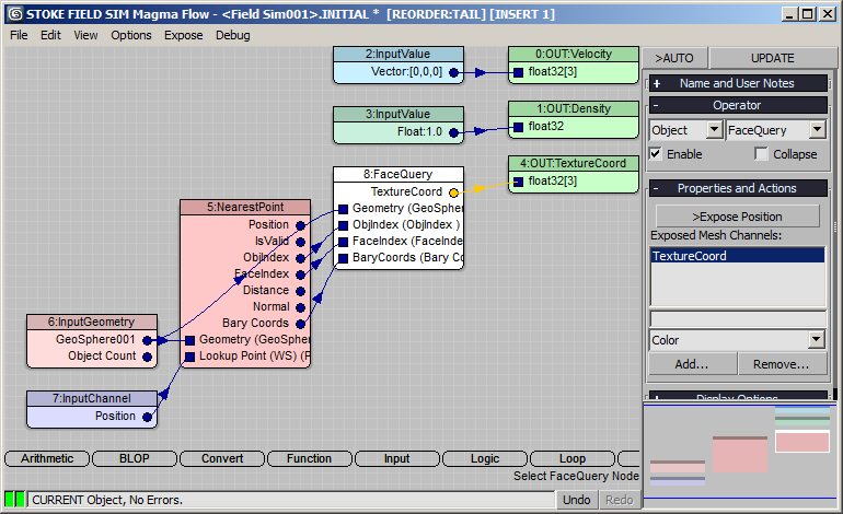
Setting Up The Initiall Flow
- Click the Open INITIAL Flow button.
- Select the Velocity output node and press SHIFT+0 to initialize to an InputValue of [0,0,0]
- Select the Density output node and press CTRL+1 to initialize to an InputValue of 1.0.
- Press SHIFT+CTRL+M to create a TextureCoord field.
- Press O for Object category, then N for NearestPoint.
- Drag from the Geometry input socket and release over an empty area of the Editor to create an InputGeometry node.
- Pick the GeoSphere as the InputGeometry source.
- Drag from the Lookup Point (WS) input socket and release to add a Position InputChannel node. Other than in Krakatoa and Genome, the Position channel in Stoke is already in World Space and thus requires no additional transformation.
- Select the NearestPoint node and press the Add Face Query button in its Properties and Actions rollout - the new node will be connected to the input nodes automatically and default to Position output.
- Scroll down in the channels drop-down list of the FaceQuery node and select TextureCoord, then press Add… to expose it as output socket.
- Unchecl >Expose Position - the Position socket will disappear and the TextureCoord socket will now be connected to the Output to be written out as a TextureCoord field.
- Close the Initial Flow.
Setting Up The Simulation Flow
- Click the Open SIMULATION Flow… button.
- Press S for Stoke category, then V for PVelocitySplat.
- Drag and release from both sockets to create an InputParticles and a Position InputChannel node.
- Pick the “PF Source 001->Even t001” event as particle input.
- Connect the Velocity output of the PVelocitySplat to the Velocity output node - this will sample the velocities of the nearest particles, remove the divergence creating fluid motion, and will create a Velocity field to advect the TextureCoord field.
- Select the Density output node and press SHIFT+D to connect a new Density InputChannel. As result, the Density of 1.0 we initialized in the other flow will just remain unchanged (but will be advected by the Velocity too).
- Press SHIFT+CTRL+M to create a new TextureCoord output and then press SHIFT+M to create an InputChannel with the same channel name. As result, the TextureCoord initialized by the other flow will persist over the duration of the simulation, and will be advected by the Velocity field as the particles move around…
- Close the Simulation Flow.

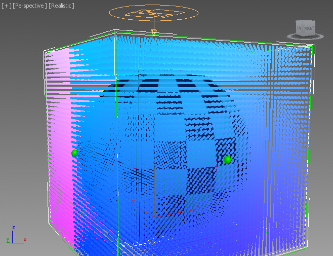
RESULT: If we would simulate now, the Initial flow will steal the mapping coordinates from the GeoSphere and put them on a grid as a vector field on the first frame of the simulation. Then the Simulation flow will sample the Velocities from the particles, put them on a grid, remove the Divergence producing fluid-like motion, and advect all other fields including the mapping coordinates to move accordingly.
After simulation, you can set the Color display to TextureCoord to visualize the mapping coordinates field as colors. Note that the UVs of a Geosphere have a high W value, resulting in mostly blueish colors.
Copying Back The Advected UVs To The GeoSphere Using Genome
In order to avoid a circulat dependency, we will need a Field Loader with the VDB file sequence saved during the simulation.
- Simply click the [+] icon next to the >Use Disk Cache button.
- Add a Genome modifier to the GeoSphere and set it to Face Corners Iteration mode.
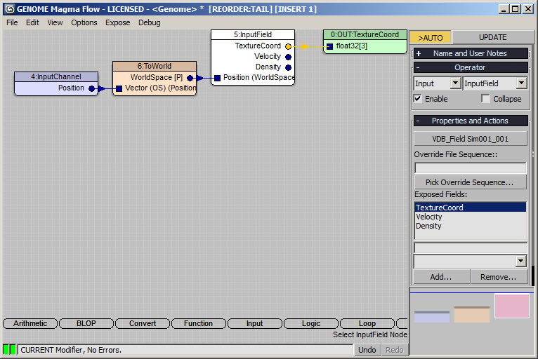
- Open the Genome Magma editor and press SHIFT+CTRL+M create a TextureCoord (Mapping) output node.
- Press I for Input category and click the InputField entry.
- Drag and release from the Position socket to create a Position InputChannel.
- Since the Position is in Object Space in Genome, but we will be sampling a Stoke Field Loader with data in World Space, press the To World button in the Input Channel parameters.
- Select again the InputField node, the click the Pick Field Object… button and pick the Field Loader called “VDB_Field Sim001_001” as the source. Make sure the TextureCoord output socket of the InputField is connected to the TextureCoord Output node:
RESULT: At this point, the GeoSphere’s Texture Coordinates will be based on the values sampled from the Field Loader. Moving the time slider should produce an animation where the particles distort the mapping.
Adjusting The Timing
Since the Velocity Field takes a frame or two to distort the UVs enough, we could offset the Field Loader by one frame to load the result earlier and better match the motion of the particles.
- Select the Field Loader and enter 1 for Offset.
- Playing back with Real Time off produces the following:
Known Limitations:
- This method does not account for the Seam where the Spherical coordinates meet on the side of the GeoSphere. Only one value will be encoded on the field for both UV vertices and an ugly seam would be visible. One workaround would be to make sure it is never seen by the camera (it is slightly visible on the left side in the above animation). Another would be to use Shrink Wrap mapping where all seams meet at the bottom where we don’t distort the texture. But this is not always a good solutuon.
- If you have to re-run the simulation because you tweaked some parameters or want a higher resolution grid etc, make sure that you
- disable the Genome modifier to initialize to the correct source UVs, and
- set the Field Loader to “Load Single Frame Only” to avoid problems as VDB files are both being read and written at the same time. Alternatively, switch the Field Simulator’s output to a new Version to avoid overwriting existing files.