Loading And Rendering External Field Data
Applicable to Stoke MX 2.0 and higher, Last Edited May 29, 2014
Overview
The following tutorial discusses the use of the Stoke Field Loader and Field Magma objects to load external field data, and render it using the Stoke Atmospheric Effect in the 3ds Max Default Scanline renderer.
Downloading Sample Data
In this example, we will use the Venus Statue dataset stored in the .VDB file format and provided by DreamWorks on the OpenVDB website.
- Download the ZIP file using the above links.
- Unzip in a folder of your choice.
Loading The Data In Stoke MX
Overview
There are several ways to handle external field data using Stoke MX.
- The Stoke Field Magma and Stoke Field Simulator objects’ Magma editor exposes an InputField node in the Input category which lets you pick a file sequence directly, or another Field object as indirect source.
- The Stoke Field Loader is one of the possible sources of the Magma InputField node. It lets you not only pick an external file sequence like the InputField node, but also control the timing and transformations of the data.
- In the cases where the external field data contains Stoke-compatible channel names like Density or Color, the Stoke Field Loader could be used directly for rendering as the source of volumetric data for the Stoke Atmospheric Effect.
- When the VDB data contains arbitrary channels not compatible with the Stoke naming conventions, it might be necessary to pass the data through a Stoke Field Magma object for conversion before rendering in the Stoke Atmospheric Effect.
- In some cases, the VDB data could also be in a different coordinate system or scale than the 3ds Max scene. The best way to tweak the data’s scale, offset and orientation is to use the Stoke Field Loader’s ability to apply transforms to a Field.
Loading And Displaying The Venus Data Set
- Start a new 3ds Max scene.
- Hold down the SHIFT key and select the “Create a Field LOADER object…” menu item from the Stoke menu in the 3ds Max Main Menu.
- Click the Pick A File Or Sequence… button and select the downloaded VENUSSTATUE.VDB file.
- Since we have a single file without animation and frame number, check the Load Single Frame Only checkbox - the exact file name selected will now be loaded on every frame.
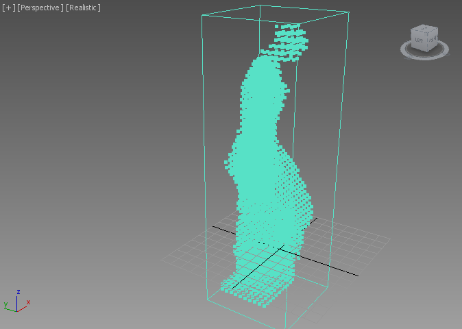
RESULT: A large box of point samples will be displayed in the viewports using the Field Loader’s object color.
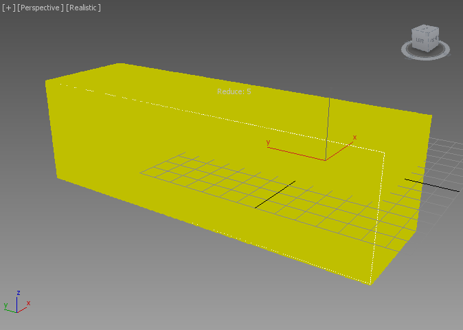
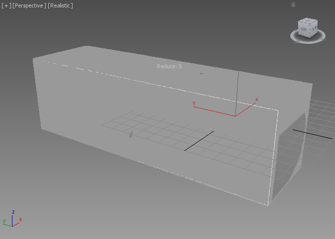
- Change the Color option from Object Color to “ls_utahteapot” (the name of the Level Set data set stored in the VDB file was obviously mistakengly left over from the conversion of a Utah Teapot!)
RESULT: The samples will now turn shades of gray.
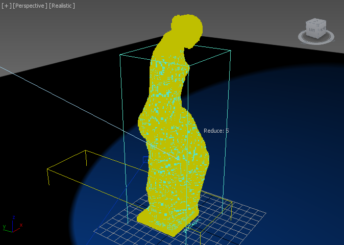
Note that since the data set contains millions of samples, the Field Loader will automatically reduce the display count to fit the host application - in 3ds Max 2015 with Nitrous and Direct3D 9 driver, it will use an automatic Reduction value of 5 to produce about 1 million samples - it skips samples and shows only every 5th sample along each axis to do so. In 3ds Max 2014 and 2013, the automatic Reduction will be even higher to produce less than 100,000 samples.
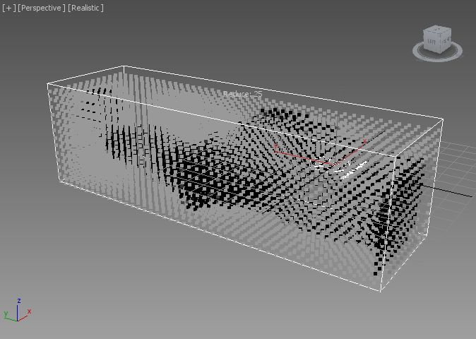
As the great Michelangelo would tell you, there is a statue hidden inside this block! Let’s peek inside:
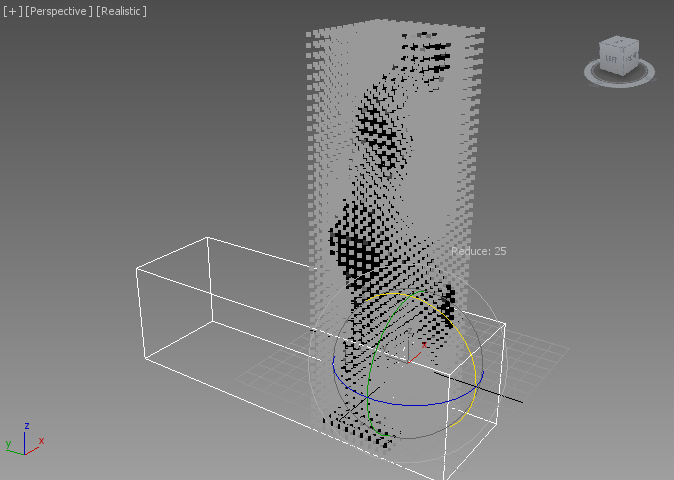
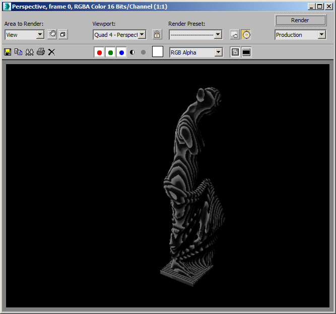
- Enter 25 in the Reduce control under the Viewport Display rollout of the Stoke Field Loader.
RESULT: This will override the automatic Reduction and show even less samples, revealing dark colors in the shape of the statue within the brighter gray surrounding box. This is because the Level Set data contains negative values inside the statue’s volume and positive values outside. Negative values show up as black, while positive is shades of gray.
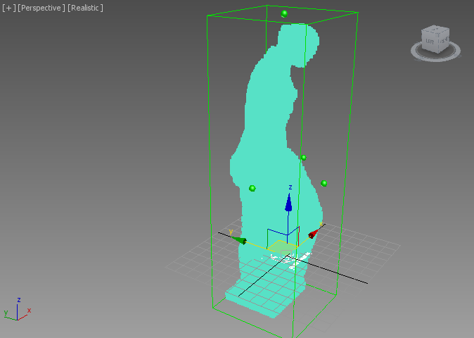
Rotating The Field
Obviously, the data was produced on a system using a Y-up coordinate system, but 3ds Max uses Z-up.
- Check the Apply Object Transforms checkbox under the Stoke Field Loader rollout.
- Rotate the Stoke Field Loader at 90 degrees about the X axis.
RESULT: The statue will now be standing vertically in the Z-up space.
Using The Stoke Field Display Modifier
The Viewport Display rollout of the Field Loader only provides very basic controls over the channels to be used. Let’s apply a more advanced display override:
- With the Field Loader still selected, click Add A Field DISPLAY Modifier to selected object(s)… from the Stoke menu.
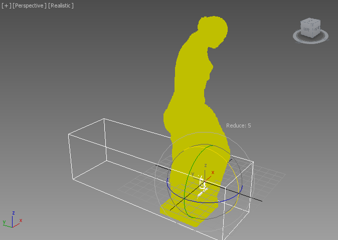
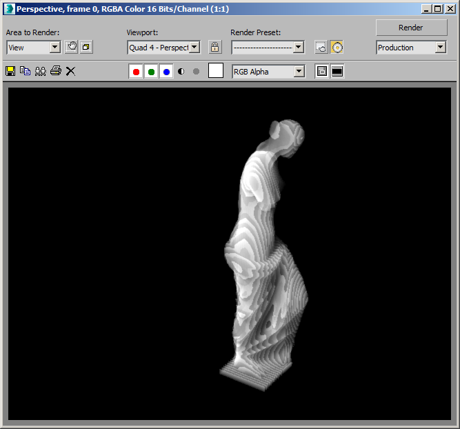
- Change the Scalar Channel Display options to “ls_utahteapot”, then check the Min and Max checkboxes to clamp the values within that range.
RESULT: The Venus Statue is now carved out of its marble block as we removed any positive values from the display.
Converting The Level Set To A Density Field
At this point, we have a Level Set downloaded from a Web site displayed in the viewports, but we cannot render it yet. This is because the data was stored in a field with name and values incompatible with the Stoke channel conventions. We will have to remap the data to convert it to Stoke Fields first before rendering it volumetrically.
Creating a Stoke Field Magma Object
- Make sure the Stoke Field Loader is still selected
- Hold down SHIFT and pick the Create a Field MAGMA object… menu item from the Stoke menu.
RESULT: A new Stoke Field Magma object will be created at the world origin, and the World Space Grid used mainly for display purposes will be adjusted to enclose the bounding box of the Field Loader.
The Conversion Magma Flow
- Press the Open Magma Editor… button.
- Press CTRL+R to enable auto-reordering.
- Select the OUT: Density node, then expand the Input category of the node depot and drag the InputField node into the editor - the two will be connected, but the new node will be displayed in red, and the Stoke Log Window will show up with an error because we don’t have a valid field yet. You can suppress the Log Window pop ups by switching the Log Level under the Help rollout of the Field Magma object to None.
- Click the pick button under Properties and Actions and pick the Field Loader from the scene, or press H and select by name from the list.
- Hide the Field Loader from the viewport - its data will still be loaded, but not drawn in the views.
- Drag a wire from the empty Position socket of the InputField node and release anywhere over the editor - a new InputChannel Position node will be created and connected to the socket.
- Select the InputField node and press L for Logic and S for Less to insert a “Less Than” logical operator into the flow - the default comparison value in the second socket is 0.0, which is exactly what we want to filter out negative values and turn them to positive.
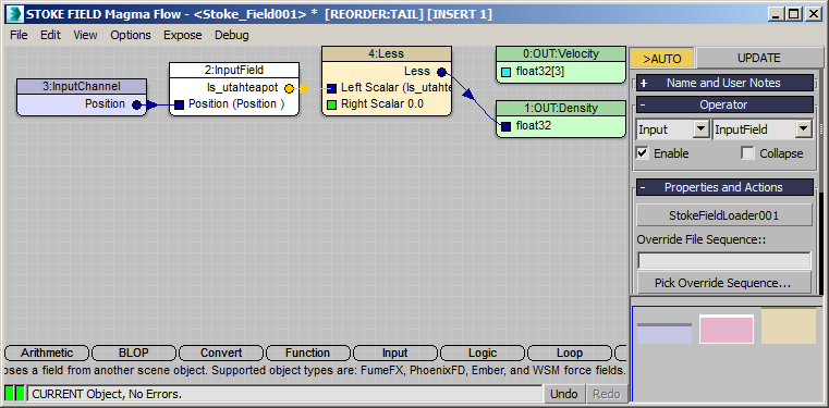
RESULT: Only the samples with negative Level Set values from the VDB will produce a positive Density value of 1, while the rest of the outside samples will be now 0 and won’t appear because the Mask control of the Field Magma object defaults to Density. This because the logical values of FALSE and TRUE are converted to 0 and 1 respectively when sent from the Logical operator to the Density Output!
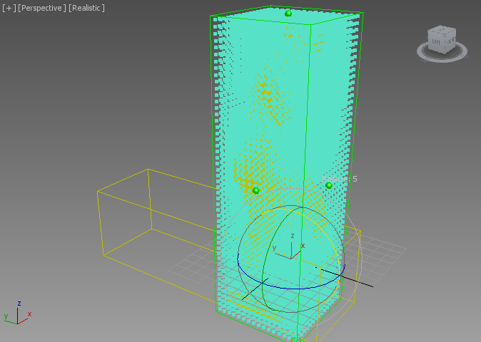
Note that the default Spacing of the World Space Grid controls the viewport display sampling of the Field Magma object. Decreaing the Spacing value to 3.0, 2.0 etc. will produce a lot more samples, but this does in no way affect how the Field Magma will sample the Level Set at render time - ALL the data will be taken into account, and interpolated as needed to produce smooth results regardless of the display and grid settings!
Here is Spacing of 2.0, producing 171,836 viewport samples in 3ds Max 2015:
Rendering The Density Field
Let’s render the resulting Density Field as a volumetric effect using the Default Scanline renderer of 3ds Max.
- In the Front View, create a Spot Light illuminating the statue from the left side.
- Open the Environment dialog of 3ds Max by going to Main Menu > Rendering > Environment.
- Press the Add… button and pick the Stoke Atmospheric effect from the list.
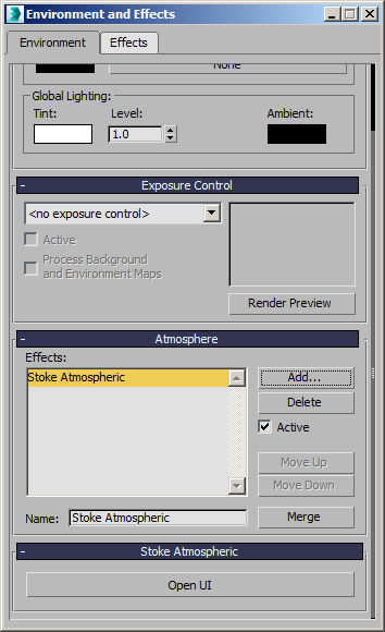
- In the Stoke Atmospheric rollout of the Environment and Effects dialog, press the Open UI button.
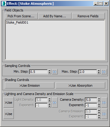
- In the Stoke Atmospheric UI, click the Pick From Scene… button and pick the Stoke Field Magma object Stoke_Field001.
- Render using the Default Scanline renderer
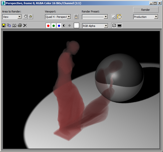
RESULT: The output won’t be correct - our Density values of the Field are too high (1.0 for every sample we loaded), and we are undersampling too much, producing visual artefacts:
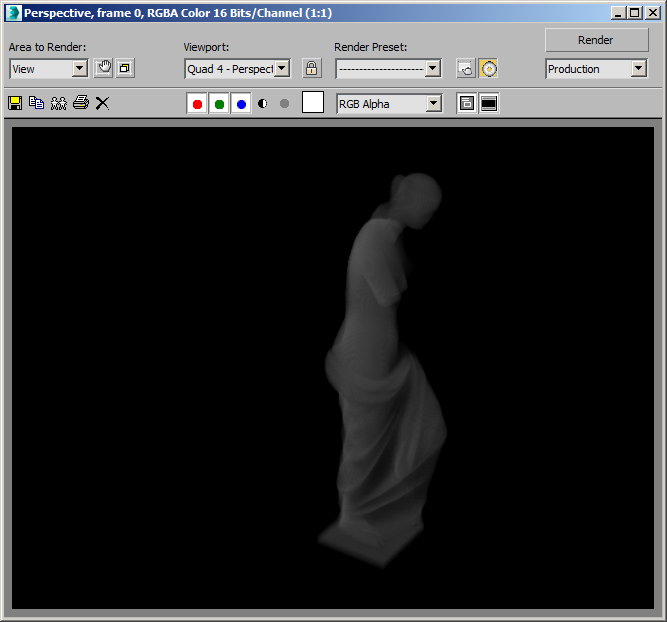
- To reduce the density, simply change the Camera Density Exponent value from -1 to -2. This will reduce the density of all rendered fields globally by one order of magnitude (10 times less):
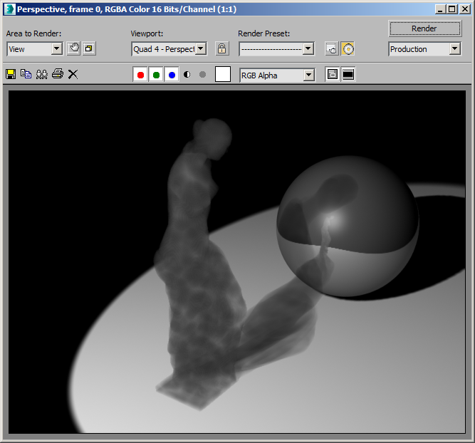
The RGB color still has the undersampling issues, but if you look at the Alpha channel, it is actually correct:
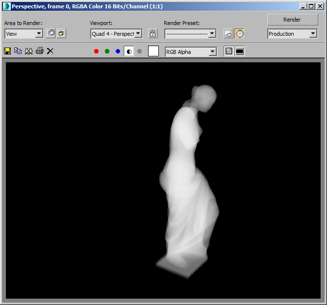
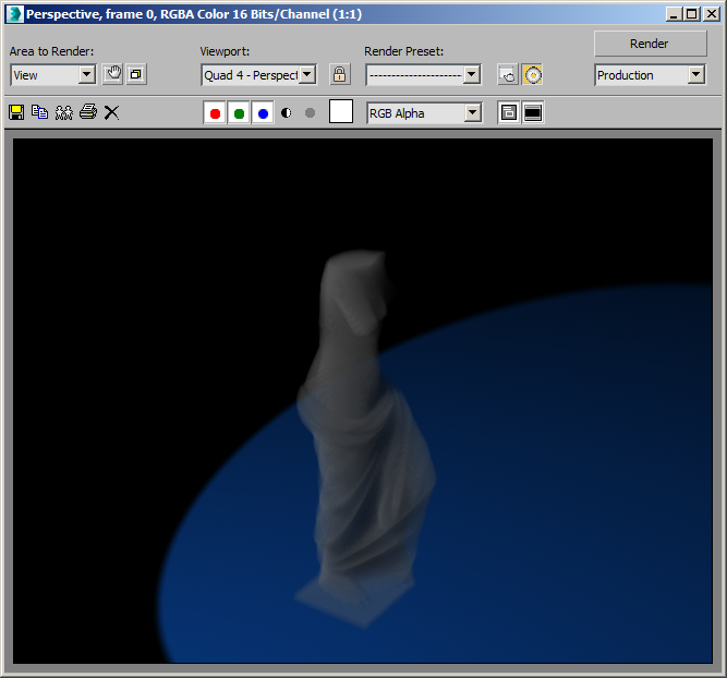
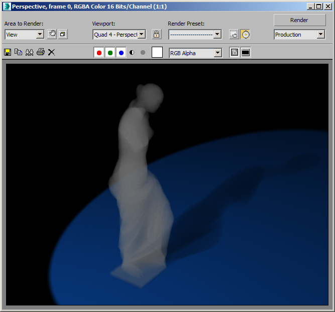
- Under Sampling Controls, change the Max.Step to 0.5 - now we are stepping through the volume with half the size of the data set, and while significantly slower, the RGB rendering will look smooth:
Integration With The Scene
The Stoke Atmospheric effect is a standard 3ds Max environment effect and can interact with scene geometry, shadow casting, raytraced reflections and refractions and so on.
NOTE: The Stoke Atmospheric is NOT supported in mental ray or iRay because it only works with the native 3ds Max atmospheric effects engine! It will work with any other renderer that supports the 3ds Max atmospherics, including V-Ray and finalRender.
Creating A Ground Plane, Moving The Base Up
- Create a Plane primitive with size of 1200 by 1200 units in the XY ground plane.
- Move the Plane to about [400,100,0].
- Unhide the Stoke Field Loader and move it up 42 units along the Z.
- Adjust the view to look at the whole statue again.
RESULT: The Loader is now outside of the original World Grid of the Field Magma object, and while the base of the statue is now on the ground plane, the head is not being sampled anymore!
Rendering now would produce a volume without the head, too!
We can solve this in different ways (and we can use this as a feature to slice through a volume and render only a subset by just adjusting the grid too!)
- Use the Grid Manipulators to manually move the top and bottom of the Grid up.
- Use the World Space Grid Size Z spinners to shift both values up (Z min to 0.0, Z max to about 230.0)
- Alternatively, with the Field Magma object selected, click the Pin Stack icon to lock the Command Panel in place and not lose the selection, then select the Field Loader and press the Get Grid Size From Selection… button in the Field Magma’s UI that is still locked in the Command Panel. The Grid will be adjusted to the new bounding box of the Field Loader, plus one voxel row padding on each side based on the automatically calculated Spacing value (in this case 4.788 based on the size of the statue’s bounding box).
Casting Shadows
- Make sure the Pin Stack icon is unchecked to allow newly selected objects to appear in the Command Panel!
- Select the Spot Light.
- Check the Cast Shadows checkbox - this is a necessary, but not sufficient condition to cast shadows from atmospheric effects!
- Expand the Shadow Parameters rollout of the Spot Light and check Atmospheric Shadows > On.
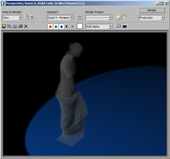
- Adjust the light position and view location to see the whole shadow on the ground plane.
RESULT: A rather solid shadow will appear on the ground.
The Stoke Atmospheric effect in Stoke 2.0 does not respect the Atmosphere Shadows > Opacity value yet. Thus, the only way to control the density of the shadow is by tweaking the Light Density in the effect itself.
- In the Stoke Atmospheric effect UI, check the >Use checkbutton in front of the Light Density/Exponent controls.
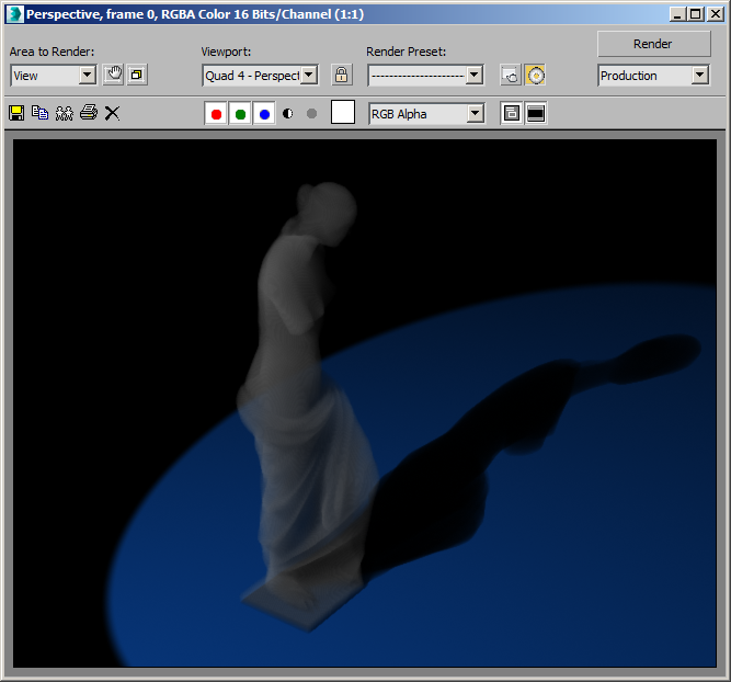
- Change the Exponent to -3. This will make the Density Field appear 10 times less dense than what the Camera sees (the Camera Exponent is -2).
- Render.
RESULT: More light passes through the statue, and the shadow on the ground is respectively less dense!
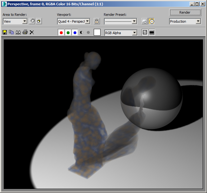
Reflections
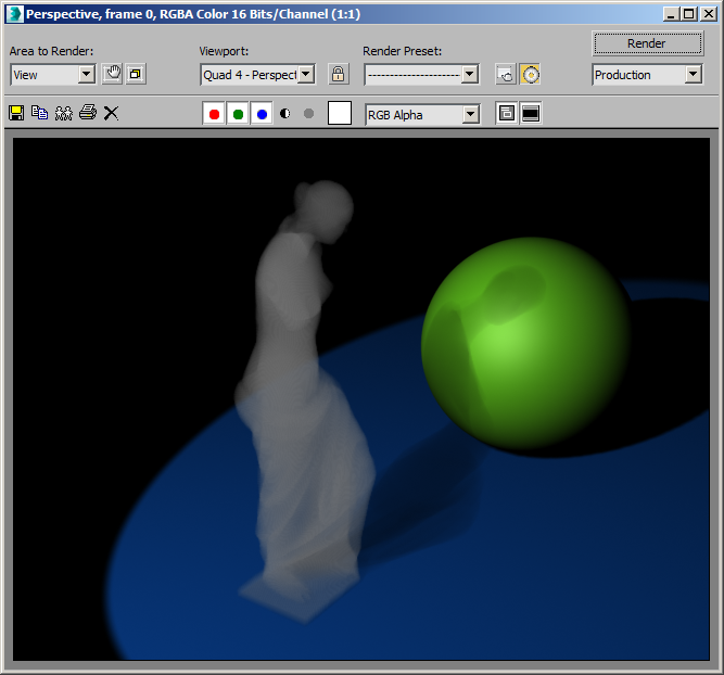
- Create a GeoSphere with “Base To Pivot” checked, Radius 80.0 and Segments 16 at about [250,0,0]
- Render.
RESULT: The shadow of the statue will fall on the Geosphere.
- Open the Material Editor
- Create a new Raytrace material
- Set the Reflect color to a Value of about 100.
- Assign to the GeoSphere.
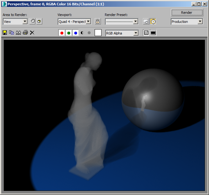
- Render
RESULT: As expected, the GeoSphere reflects the Stoke Atmospheric.
Controlling The Color
As we can see from the above examples, the Stoke Atmospheric effect assumes the Color of the Density Field to be white because there is no explicit Color Field. This is different from the way Krakatoa can use the Object Color as implicit Color source.
Creating A Simple Color Field
Let’s provide an explicit Color Field via our Magma setup.
- Select the Field Magma object.
- Open the Magma Editor.
- Select the unused Velocity Output node and change its channel to Color by picking from the Standard Channel Names list.
- With the Color Output node still selected, press SHIFT+1 to create a pure red [1,0,0] Vector InputValue.
- Select the Plane primitive and assign a Standard material with pure white Diffuse color.
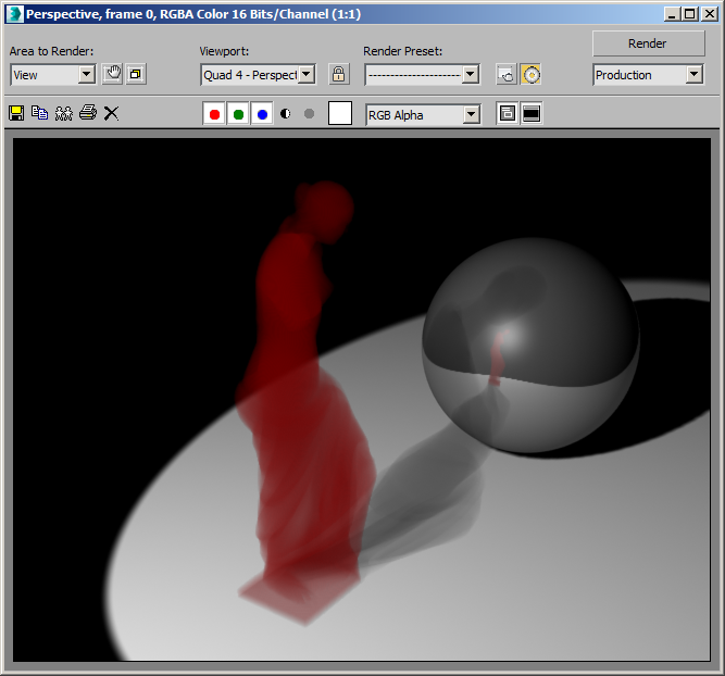
- Render.
RESULT: The Stoke Atmpospheric is now red. You will notice though that the shadow on the ground did NOT turn red. The Color field only controls the volumetric scattering of light into the Camera, but we need the Absorption channel to define how light is attenuated as it passes through the volume.
Creating A Simple Absorption Field
Like we did with the Color, let’s define an Absorption field.
- In the Magma Editor, press SHIFT+CTRL+B to create an Absorption output node (the A key is used for Age, so B was the next key available…)
- With the node still selected, press SHIFT+4 to create and connect a Cyan InputValue [0,1,1] - this is the complementary color to red (white-red=cyan!)
- Disable the Color output by selecting it and unchecking the Enable checkbox - we want a white field absorbing the green and blue components of the white light passign through them, thus turning into red color and red shadow! Alternatively, we can keep the Color channel enabled and change the InputValue to [1,1,1] white.
- Render.
RESULT: As expected, the white light is attenuated to reddish as the green and blue components are being absorbed very quickly.
You can use the second (Complement) color picker underneath the As Color picker in the InputValue of Magma to define the color you expect white particles lit by white light to turn into.
Texture Mapped Absorption
Instead of using a constant value, we can use any available method in Magma to produce a different value at every sample point. For example, let’s use a 3D procedural texture map.
- Delete the InputValue connected to the Absorption output node.
- Select the Absorption output and press O for Object category and T for TexmapEval node - the Color output will be connected to the Absorption.
- Drag a connection from the Lookup Point (OS) to the existing Position InputChannel node.
- In the TexmapEval node, pick a Cellular map as the texture to use.
- Render.
RESULT: The volume will have varying Absorption, but since the Cellular map defaults produce a grayscale Color, there is no difference between the absorption of R, G and B.
- In the Compact Material Editor, select an unused sample sphere.
- In the Magma Editor, press the Put To MEdit button in the TexmapEval node.
- Adjust the Cell Color to [0,100,255]
- Adjust the first Division Color to [255,200,64]
- Render.
RESULT: The Cell color (Blue) now produces Orange colors (its complementary color) as the White light passes through the White volume and loses its Blue channel faster than the Green, while the Orange color of the Division produces bluish color as it absorbs the Red and Green.