FROST MX User Interface Rollouts

Frost Rollout

../../_images/FROST_Rollouts_Frost.png
UI Element UI Element Type Description
Options Group  
Icon Checkbox
  • When checked, the Frost icon will be displayed in the viewport.
Icon Size Value Spinner
  • Defines the size of the Frost viewport icon.
Velocity to Map Channel Checkbox
  • When checked, the Velocity will be written to the specified Map channel of the Frost mesh.
Map Channel Value Spinner
  • Specifies the Map channel to copy the Velocity data into.
  • Default is 2.
Viewport Update Group
  • Controls when the FROST mesh is rebuilt.
  • Building the mesh can take a while, so you may want to limit how often it is done.
When Frost Changes Checkbox
  • When checked, the mesh will be rebuilt whenever a parameter in a Frost rollout is changed.
When Particles Change Checkbox
  • When checked, the mesh will be rebuilt when an object in the Particle Object list changes.
Force Viewport Update Button
  • Rebuilds the mesh when pressed.

Help Rollout

../../_images/FROST_Rollouts_Help.png
UI Element UI Element Type Description
Open Online Help… Button
  • Opens the Frost Online Help in the default web browser.
  • Requires internet connection
Show Log Window Button
  • Displays the Frost Log Window.
  • The Log Window lists errors, warnings, and other messages from Frost.
Log Options >> Menu Button
  • Displays a menu with just one option:
  • Show Log Window On Errors - opens the Log Window automatically when an error occurs.

Frost Log Window

  • The Frost Log Window displays errors, warnings, and other messages from FROST.
  • It can be shown by clicking the Show Log Window button in the Help Rollout.

Log Window Pop-up

  • By default, the log window will pop up when Frost reports an error or warning.
  • To disable this pop-up, uncheck “Show Log Window on Errors” using the [>>] Options menu next to the Show Log Windows button.

Presets Rollout

  • The Presets Rollout allows you to manage custom presets of parameter values that can be applied to any other FROST object.
  • To load a preset and apply its settings to the current FROST object, simply click on a preset name in the Preset List
../../_images/FROST_Rollouts_Presets.png
UI Element UI Element Type Description
Save… Button
  • Saves the current FROST object settings to a presets file.
  • Press to open a new dialog, allowing you to specify which parameters to be saved.
  • By default, all parameters except for the icon size will be highlighted.
  • Use Ctrl+Click and SHIFT+Click or the Add, Invert and Default buttons to highlight the controls you want to save.
  • Enter the name of the preset in the Name field.
  • Press the SAVE PRESET button to save, or CANCEL to exit.
Set Default… Button
  • Sets the currently highlighted preset as the default to load when a new object is created.
  • To disable the default preset loading on new object creation and use the factory defaults,
    • Highlight the Custom Settings entry,
    • Press Set Default.
    • Answer the prompt to confirm the operation.
Delete… Button
  • Deletes the currently selected preset file from disk.
Explore… Button
  • Opens the folder containing the preset files in Windows Explorer.
  • Used to manage preset files, for example to copy presets to other computers, email them to friends and so on.

Particle Objects Rollout

  • The Particle Objects rollout allows you to choose scene particle sources to mesh using FROST.
  • If you’d like to mesh a particle data file instead, see the Particle Files Rollout.
../../_images/FROST_Rollouts_ParticleObjects.png
UI Element UI Element Type Description
Pick Button
  • Select a single particle object to add from the viewport.
  • Right-click or click the Pick button again to cancel.
Add… Button
  • Launch a dialog box that allows you to select particle objects from the scene by name.
Particle Object List Box
  • A list of objects that add particles to this FROST object.
Remove Button
  • Remove the selected particle objects from the particle object list.
Options >> Menu Button
  • Opens a context menu with options to clean up, reorder or sort the Particle Objects list in various ways:
  • Select Highlighted In the Scene
Menu Item
  • Selects in the scene the objects that are highlighted in the Particle Objects list.
  • Remove Deleted Objects
Menu Item
  • Cleans up the Particle Objects list by removing any entries left from objects that have been deleted from the scene.
  • Highlight In List >
Sub-Menu
  • This menu offers several commands to highlight objects on the list.
  • Highlight In List > All
Sub-Menu Item
  • Highlights all entried in the Particle Objects list.
  • Highlight In List > Invert
Sub-Menu Item
  • Inverts the highlighted entries in the Particle Objects list.
  • Highlight In List > Similar
Sub-Menu Item
  • Highlights the objects of the same class as the highlighted object.
  • Move Highlighted >
Sub-Menu
  • This Sub-Menu offsers several commands to move objects up and down the list.
  • Move Highlighted > To Top
Sub-Menu Item
  • Moves one or more highlighted objects to the top of the list, preserving their relative order.
  • Move Highlighted > One Object Up
Sub-Menu Item
  • Moves exactly one highlighted object up one position.
  • The selection will be preserved, allowing multiple clicks to move several positions up.
  • Grayed out if there are more than one highlighted objects or the top most object is highlighted.
  • Move Highlighted > One Object Down
Sub-Menu Item
  • Moves exactly one highlighted object down one position.
  • The selection will be preserved, allowing multiple clicks to move several positions up.
  • Grayed out if there are more than one highlighted objects or the bottom most object is highlighted.
  • Move Highlighted > To Bottom
Sub-Menu Item
  • Moves one or more highlighted objects to the bottom of the list, preserving their relative order.
  • Sort >
Sub-Menu
  • This Sub-Menu offsers several commands to sort the objects on the list.
  • Sort > Ascending Alphabetical Order
Sub-Menu Iten
  • Sorts the whole list in Alphabetical order in ascending order, from A to Z and a to z.
  • Sort > Descending Alphabetical Order
Sub-Menu Iten
  • Sorts the whole list in Alphabetical order in descending order, from z to a and Z to A.
  • Sort > Scene Creation Order
Sub-Menu Iten
  • Sorts the whole list in scene creation order from oldest to newest, reflecting the order of the scene tree.
  • Note that linking and then unlinking a child from its parent will send it to the end of the scene tree.
  • Sort > Object Type
Sub-Menu Iten
  • Reorders the current list by object class.
  • For example all Boxes, all Particle Flows, all SphereGizmos in their own consecutive blocks.
  • Sort > Reverse Current Order
Sub-Menu Iten
  • Flips the current order of the list regardless of how it was achieved.
  • E.g. to sort by newest to oldest creation order, call “Sort In Scene Creation Order”, then “Reverse Current Order”.

Particle Flow Events Rollout

  • The parameters in this rollout control which Particle Flow Events add particles to FROST.
  • Note that a Particle Flow object can only contribute particles if it is in the Particle Objects list in the Particle Objects Rollout.
../../_images/FROST_Rollouts_PFlow_Event.png
UI Element UI Element Type Description
All Events Radio Button
  • When this is selected, FROST will use particles from all Particle Flow events.
Selected Events Radio Button
  • Only use particles that are in Events listed in the Particle Flow Events list, which is described below.
  • The following controls are enabled only if you choose Selected Events:
Edit… Button
  • Shows the Select Particle Flow Events Dialog, which lets you add or remove Events in the Particle Flow Events list.
Remove Button
  • Removes the selected Events from the Particle Flow Events list.
Options >> Menu Button
  • Displays a context menu with the option “Remove Deleted Events”.
  • Use to clean up <Deleted> entries from the list belonging to Events that have been deleted from Particle View.
Particle Flow Events ListBox
  • The list of Particle Flow Events that will be included in the FROST mesh.

Select Particle Flow Events Dialog

  • The Select Particle Flow Events dialog lets you add and remove events from the Particle Flow Events list in the Particle Flow Events Rollout.
  • You can show this dialog by clicking the Edit… button in the Particle Flow Events Rollout of the Frost UI.
../../_images/select_pflow_events.png
  • This dialog has two event lists.
    • The left list, titled Ignore Events, shows events whose particles will be excluded from the Frost mesh.
    • The right list, titled Get Particles from Events, shows events whose particles will be included in the Frost mesh.
  • To move events between the two lists:
    • Click the [>] and [<] buttons, located between the two lists, to move the selected events from one list to the other.
    • Double click on an event to move it from one list to the other.

Thinking Particles Groups Rollout

  • The parameters in this rollout control which Cebas Thinking Particles Groups add particles to FROST.
  • This rollout is visible only if you have Cebas’ Thinking Particles installed.
  • Note that a Thinking Particles object can only contribute particles if it is in the Particle Objects list in the Particle Objects Rollout.
../../_images/FROST_Rollouts_thinkingParticles_Groups.png
UI Element UI Element Type Description
All Groups Radio Button
  • When this is selected, FROST will use particles from all ThinkingPartices Groups.
Selected Groups Radio Button
  • Only use particles that are in Groups listed in the Thinking Particle Groups list, which is described below.
  • The following controls are enabled only if you choose Selected Groups:
Edit… Button
  • Shows the Select Thinking Particles Groups Duakig, which lets you add or remove Groups in the TP Groups list.
Remove Button
  • Removes the selected Groups from the Thinking Particles Groups list.
Options >> Menu Button
  • Displays a context menu with the option “Remove Deleted Groups”.
  • Use to clean up <Deleted> entries from the list belonging to Groups that have been deleted from Thinking Particles.
Thinking Particles Groups ListBox
  • The list of Thinking Particle Groups that will be included in the FROST mesh.

Select Thinking Particles Groups

  • The Select Thinking Particles Groups dialog lets you add and remove events from the Thinking Particles Groups list in the Thinking Particle Groups Rollout.
  • You can show this dialog by clicking the Edit… button in the Thinking Particles Groups Rollout of the Frost UI.
  • This dialog has two group lists.
    • The left list, titled Ignore Groups, shows groups whose particles will be excluded from the Frost mesh.
    • The right list, titled Get Particles from Groups, shows groups whose particles will be included in the Frost mesh.
  • To move groups between the two lists:
    • Click the [>] and [<] buttons, located between the two lists, to move the selected groups from one list to the other.
    • Double click on a group to move it from one list to the other.

Particle Files Rollout

  • The Particle Files rollout allows you to add particle data files to mesh using FROST.
  • If you’d like to mesh a scene particle object instead, see the Particle Objects Rollout.
../../_images/FROST_Rollouts_ParticleFiles.png
UI Element UI Element Type Description
Add… Button
  • Opens a Select the Particle File Sequence dialog.
  • To add a particle file sequence, select any file from the sequence, and press Open.
Remove… Button
  • Remove the selected files from the File List.
File List ListBox
  • A list of the particle files being used by this FROST object.
Reload Source Sequences Button
  • Reload all of the particle files for the current frame.
Timing Group
  • Encloses all Time-related controls
Load Single Frame Only Checkbox
  • When checked, loads the exact particle file listed, and does not attempt to load a file for the current time.
Use Playback Graph Checkbox
  • When checked, enables the Playback Graph control, which is described below.
Playback Graph Value Spinner
  • This animatable parameter controls which file frame number is loaded for each scene frame.
Frame Offset Value Spinner
  • This offset is added to the scene frame number to calculate the particle file frame number.
  • For example, scene time 32 with Frame Offset of 10 will load frame number 42 from the file sequences.
Limit To Custom Range Checkbox
  • When enabled, FROST will only load frame numbers inside the range given by the First Frame and Last Frame controls.
Range Button
  • Attempt to find a frame range that is present in all of the sequences in the Particle Files list.
    • If a range is found, then the First Frame, Last Frame, and Limit To Custom Range controls will be set.
    • If no common range can be found, then a warning dialog box will appear instead.
First Frame Value Spinner
  • When Limit To Custom Range is enabled, this is the lowest frame number that FROST may load.
Last Frame Value Spinner
  • When Limit To Custom Range is enabled, this is the highest frame number that FROST may load.
Before Range Behavior Dropdown List
  • Control what particles FROST will use for frames before the First Frame.
    • Hold First will load the first frame on all frames before the First Frame.
    • Blank will load no particles.
After Range Behavior Dropdown List
  • Control what particles FROST will use for frames after the Last Frame.
    • Hold Last will load the last frame on all frames after the Last Frame.
    • Blank will load no particles.
File Units Dropdown List
  • Specify the unit of length in the particle files.
    • FROST will convert this into 3ds Max system units.
    • See File Units Scaling for more information.

Region Of Interest Rollout

  • Control an optional world-oriented box-shaped region that can be used to limit the FROST meshing to a specific area.
  • See the Region Of Interest Meshing topic for more information.
  • The following options are available:
../../_images/FROST_Rollouts_RegionOfInterest.png
UI Element UI Element Type Description
Use Region Of Interest Checkbox
  • Toggles on and off the use of the ROI in both Viewport and Renderer with one click.
Render Checkbox
  • Toggles on and off the use of the ROI in the Renderer.
Viewport Checkbox
  • Toggles on and off the use of the ROI in the Viewport.
Show Manipulator Checkbutton
  • Toggles on and off the Select and Manipulate mode of 3ds Max.
  • When checked, and if the Use… checkbox is not unchecked, the ROI Manipulator will become visible.
  • The button is disabled when the Use… checkbox is unchecked.
Region Center Group of Spinners
  • Contains three value spinners defining the world space X, Y and Z center position of the Region Of Interest gizmo.
  • Default value for all three spinners is 0.0 which places the gizmo around the world origin.
Region Size Group of Spinners
  • Contains three value spinners defining the world space X, Y and Z extents of the Region Of Interest gizmo.
  • Default value for all three spinners is 100.0.

Material Rollout

  • Control how the Material IDs are set in the FROST mesh.
  • The following options are available:
../../_images/FROST_Rollouts_Material.png
UI Element UI Element Type Description
Material Dropdown List
  • Controls the Material ID generation mode:
Single Material ID List Option
  • The entire FROST mesh will have Material ID 1.
ID from MtlIndex Channel List Option
  • The Material ID will be set from the particles’ MtlIndex channel.
ID from Shape Number List Option
  • Requires Meshing Mode: Geometry
  • Each Shape on the Custom Geometry list will be assigned a Material ID.
  • For example,
    • the first object in the Custom Geometry list will get Material ID 1,
    • the second object in the list will get Material ID 2, etc.
ID from Geometry List Option
  • Requires Meshing Mode: Geometry
  • The FROST mesh will keep the same Material IDs as the objects in the Custom Geometry list.
Material from Geometry List Option
  • Requires Meshing Mode: Geometry
  • The FROST mesh will use the same materials as the Custom Geometry objects.
  • Press the Create Material button to build a Multi/Sub-Material and apply it to the FROST object.
Create Material Button
  • Available only in Material from Geometry mode (see above).
  • Builds a Multi/Sub-Material from the Custom Geometry Materials and applies it to the FROST object.

Meshing Rollout

../../_images/FROST_Rollouts_Meshing.png
UI Element UI Element Type Description
Meshing Mode Dropdown List
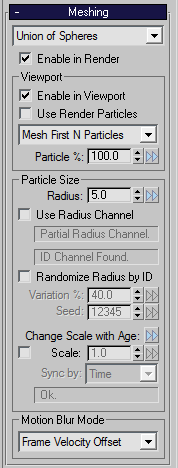
  • This drop-down controls the particle meshing mode.
  • See Meshing Modes for more information.
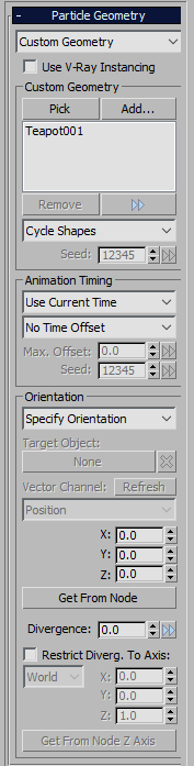
Meshing Mode > Geometry List Option
Meshing Mode > Union Of Spheres List Option
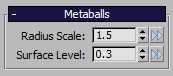
Meshing Mode > Metaballs List Option
  • Makes a standard “marching cubes” iso-surface mesh - see Metaballs.
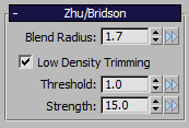
Meshing Mode > Zhu/Bridson List Option
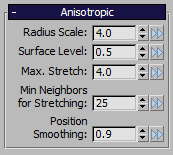
Meshing Mode > Anisotropic List Option
Enable in Render Checkbox
  • Enables mesh creation during rendering.
  • When disabled, FROST will produce an empty mesh at render time.
Viewport Group
  • Viewport-related Meshing controls.
Enable in Viewport Checkbox
  • Controls the mesh creation in the viewport.
  • When disabled, FROST will produce an empty mesh in the viewport.
Use Render Particles Checkbox
  • Some particle sources generate different particles in the viewport and render.
  • When enabled, FROST will use the render particles to create the viewport mesh.
Load Mode Dropdown List
  • Controls the order of loading when reading only a fraction of the particles:
Load Mode > Mesh First N Particles List Option
  • Load particles from the beginning of each particle source until the desired count is reached.

    If the particles are ordered (for example saved from geometry primitives, or emitted over time), this mode will show only a small region that is unrepresentative of the overall shape of the particle cloud, but since loading just a portion of the file is much faster than reading the whole file, it was made the default setting.

    If the particles in the cloud are completely random (unordered), the result of this mode will look like the result of Mesh Every Nth Particle but without the speed hit.

Load Mode > Mesh Every Nth Particle List Option
  • Balance loading through the files, skipping particles to reach the final count.

    If the particles are ordered (for example saved from geometry primitives, or emitted over time), this mode will display a lower particle count that would still represent the overall shape of the particle cloud correctly.

    On the negative side, this mode requires each particle object on the current frame to be opened and read from start to end, making this mode the slower one.

Load Mode > Mesh Every Nth by ID List Option
  • Balance loading through the files, skipping particles based on the ID channel (if present) to reach the final count.

    If every particle has a unique ID, the same particles will be loaded even if other particles are born or die, resulting in a stable flicker-free particle cloud over time.

    This method has the same speed drawback as Mesh Every Nth Particle.

Particle % Value Spinner
  • Defines the percentage of particles (first N or every Nth) to be meshed as fraction of the total particle count.
Particle Size Group
  • Controls related to the size of the particles.
Radius Value Spinner
  • Defines a base particle radius.
Use Radius Channel Checkbox
  • When enabled, particles will get their radius from their own radius information.
  • Particles that do not have radius information will use the value in the Radius control instead.
Radius Channel Status Indicator Text Field
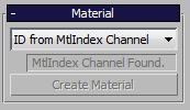
ID Channel Status Indicator Text Field
  • Indicates whether the ID channel is available.
Randomize Radius by ID Checkbox
  • When checked, a variation will be added to the size of particles.
  • This only affects particles that get their radius from the Radius control.
  • The Variation control(see below) controls how much variation is used.
Variation % Value Spinner
  • When Randomize Radius by ID is enabled, this is the fraction of the Radius control value that will vary randomly.
  • The Maximum Radius is given by the Radius control, the Minimum Radius is (1 - Variation/100.0) * (Maximum Radius).
Seed Value Spinner
  • A random seed that is combined with the particle ID to produce random variation.
Change Scale with Age >> Menu Button
  • Preset options for changing the size of particles over their lifespan.
  • These options set the value of the animated Scale and Synch by controls, below.
Scale Checkbox Value Spinner
  • When checked, the Radius will be multiplied by the Scale to calculate the particle radius.
  • The Scale can be animated according to the particle age by using the Synch by control, below.
Synch by Dropdown List
  • Controls how an animated Scale is applied to the particles.
Synch by > Time List Option
  • The Scale of all particles is animated using the scene time.
Synch by > Age List Option
  • The Scale is animated using the Age channel of the particles.
Synch by > Life % List Option
  • The Scale is animated using the lifespan percentage of the particles.
  • The Life % is 0 at a particle’s birth, and is 100 at its death. This is calculated as 100 * Age / LifeSpan.
Motion Blur Mode Dropdown List
  • Controls how the mesh is created for subframes between integer frame numbers.
Mo.Blur > Frame Velocity Offset List Option
  • A mesh is created for each integer frame.
  • For subframes, the whole frame mesh is offset using the particle velocity.
  • This keeps the mesh topology consistent within the half-frame before and after each frame.
  • This is necessary for correct motion blur in most geometry renderers incl. V-Ray, mental ray and finalRender.
  • See Motion Blur Modes for more information.
Mo.Blur > Subframe Particle Position List Option
  • A mesh is created for each subframe.
  • This is useful for multi-pass motion blur rendering where topology changes do not matter.
  • See Motion Blur Modes for more information.

Meshing Quality Rollout

  • This rollout is visible only if you choose Union of Spheres, Metaballs, Zhu/Bridson, or Anisotropic in the Meshing Rollout.
../../_images/FROST_Rollouts_MeshingQuality.png
UI Element UI Element Type Description
Resolution Group
  • The Union of Spheres, Metaballs, Zhu/Bridson and Anisotropic meshing modes work by sampling a density field.
  • These controls let you adjust how many samples are taken from the density field.
  • More samples may capture finer details, but will take more time and the resulting mesh will require more memory.
  • Relative to Max. Radius
  • Render
  • Viewport
  • Radio Button
  • Value Spinner
  • Value Spinner
  • Defines the number of samples taken along the length of the radius of the largest particle.
  • A higher number produces a mesh with more faces, which takes longer to build.
  • Because it is relative to the particle size, it keeps a similar mesh quality as the radius is adjusted / animated.
  • However, if the Max. Radius gets very large, small detail from small particles could be lost.
Up/Down Arrows Arrow Buttons
  • Pressing the Down Arrow converts the Relative settings to Absolute Settings.
  • Pressing the Up Arrow converts the Absolute settings to Relative Settings.
    • For example, you have set up a good Relative resolution according to the current radius values.
    • You want to “freeze” this resolution for the whole animation regardless of changing radii.
    • You can press the Down Arrow button to produce the needed Absolute settings.
  • Absolute Spacing
  • Render
  • Viewport
  • Radio Button
  • Value Spinner
  • Value Spinner
  • Define the absolute distance between samples, measured in world units, for rendering and viewport display.
  • A lower number produces a mesh with more faces, which takes longer to build.
  • This Resolution is independent of the particle size.
  • It is useful for keeping the mesh look consistent when particles have different animated radii.
  • Vertex Refinement
  • Render
  • Viewport
  • Group
  • Value Spinner
  • Value Spinner
  • Control the number of iterations used to move the mesh closer to the exact surface.
  • A higher number produces a mesh that is a better fit for the surface, but takes longer to build.
  • A higher number produces a mesh that is a better fit for the surface, but takes longer to build.
Use Viewport Settings Checkbox
  • When checked, the settings you see in the viewport will be used for rendering.

Metaballs Rollout

  • This rollout is visible only if you select Metaballs in the Meshing Rollout.
../../_images/FROST_Rollouts_Metaballs.png
UI Element UI Element Type Description
Radius Scale Value Spinner
  • A particle will affect space up to a distance of (radius * Radius Scale) away from the particle.
  • This distance is the particle’s effect radius the influences the Density Field that produces the Mesh.
Surface Level Value Spinner
  • A particle adds density in the space surrounding the particle.
  • This density is greatest at the particle’s center, and decreases to zero at the particle’s effect radius.
  • The mesh will be created where the combined density from all particles equals this Surface Level.
  • Increasing the Surface Level will move the mesh closer to the particles.
  • Decreasing the Surface Level will move the mesh farther away.

Zhu/Bridson Rollout

  • This rollout is visible only if you select Zhu/Bridson in the Meshing Rollout.
../../_images/FROST_Rollouts_ZhuBridson.png
UI Element UI Element Type Description
Blend Radius Value Spinner
  • Zhu/Bridson meshing blends the surface between nearby particles.
  • The blending distance is determined by (maximum particle radius * Blend Radius).
Low Density Trimming Checkbox
  • Each particle contributes a density that is highest at its center, and that decreases to zero away from the particle.
  • When Low Density Trimming is enabled, the mesh volume is removed from low-density regions.
Threshold Value Spinner
  • Regions under this density will be affected by low density trimming.
Strength Value Spinner
  • Defines the strength of the low density trimming effect.
  • This meshing method is based on the method described in:

Yongning Zhu and Robert Bridson. “Animating Sand as a Fluid”. ACM Transactions on Graphics, vol 24, number 3, pp 965-972, July 2005.

Anisotropic Rollout

  • This rollout is visible only if you select Anisotropic in the Meshing Rollout.
../../_images/FROST_Rollouts_Anisotropic.png
UI Element UI Element Type Description
Radius Scale Value Spinner
  • Multiplies the radius of the particles.
  • This also scales the size of the neighborhood that is used to stretch the particles and smooth their positions.
Surface Level Value Spinner
  • A particle adds density in the space surrounding the particle.
  • This density is greatest at the particle’s center, and decreases to zero at the particle’s effect radius.
  • The mesh will be created where the combined density from all particles equals this Surface Level.
  • Increasing the Surface Level will move the mesh closer to the particles.
  • Decreasing the Surface Level will move the mesh farther away.
Max. Stretch Value Spinner
  • Particles are stretched to fit the shape of the nearby surface.
  • The Max Stretch is the greatest multiplicative difference allowed between the stretch in different directions.
  • Max Stretch of 1 corresponds to a sphere with no stretching, while higher values allow stretched ellipsoids.
Min Neighbors for Stretching Value Spinner
  • The number of particles required near a particle to allow stretching.
  • With less than this number of neighboring particles, the particle will be shaped as a sphere.
Position Smoothing Value Spinner
  • Particles are moved toward their neighbors to smooth out lumps the mesh surface.
  • Position Smoothing controls the strength of this smoothing effect.
  • 0 means no smoothing, while 1 applies the full smoothing effect.
  • This meshing method is based on:

Jihun Yu and Greg Turk. “Reconstructing Surfaces of Particle-Based Fluids Using Anisotropic Kernels”. ACM SIGGRAPH Symposium on Computer Animation (2010).

Particle Geometry Rollout

  • This rollout is visible only if you select Geometry in the Meshing Rollout.
../../_images/FROST_Rollouts_ParticleGeometry.png
UI Element UI Element Type Description
Geometry Source Dropdown List
Use V-Ray Instancing Checkbox
Custom Geometry Group
  • Contains the controls visible when in Custom Geometry mode.
  • This also scales the size of the neighborhood that is used to stretch the particles and smooth their positions.
Pick Pick Button
  • Picks a scene object in the viewport to add to the Custom Geometry List.
  • You can cancel by right-clicking or by pressing the Pick button again.
Add… Button
  • Show a dialog box of objects that you can choose to add to the Custom Geometry list.
Custom Geometry List ListBox
  • A list of objects whose meshes can be used to define particle shapes.
Remove Button
  • Removes the highlighted items from the Custom Geometry list.
Options Menu >> Menu Button
  • Provides useful options to reorder or sort the list.
Custom Geometry Selection Mode Dropdown List
  • Defines how the Custom Geometry is selected for each particle from the list.
Cycle Shapes List Option
  • The first particle gets the first Custom Geometry list entry, the second particle the second, and so forth.
  • If the particle order changes between frames, there will be fluctuation in the shapes assigned to some particles.
Random Shape by ID List Option
  • A particle’s ID is combined with the Seed to choose a random shape from the list.
  • Given the same ID and Seed, a particle will always pick the same shape from the list on each frame.
Use ShapeIndex channel List Option
  • An integer channel named ShapeIndex is used choose a list entry for each particle.
  • The first entry in the list has ShapeIndex 1, out of range values are wrapped around.
  • The channel can be defined using Krakatoa Magma.
Seed Value Spinner
  • The random seed that is combined with the particle ID to choose a shape for each particle in Random Shape by ID mode.
Animation Timing Group
  • Contains the controls affecting the Custom Geometry animation synchronization.
Animation Timing Base Mode Dropdown List
  • Control the base time the geometry is sampled at.
Use Time 0 List Option
  • The geometry’s mesh will be taken from time 0, animation will be ignored.
Use Current Time List Option
  • The geometry’s mesh will be taken from the current frame time.
Animation Timing Offset Mode Dropdown List
  • This is combined with the Animation Timing Base Mode to control what time the geometry is sampled at.
No Time Offset List Option
  • Sample the geometry at the base time.
Random Offset By ID List Option
  • Choose a random time offset based on the particle ID and the Seed.
Add GeomTime Channel List Option
  • The GeomTime channel is added to the base time. The GeomTime unit is frames.
Max Offset Value Spinner
  • The maximum time offset to use when Random Offset By ID is selected. This is measured in frames.
Seed Value Spinner
  • A particle’s ID is combined with this seed value to choose a random time offset for Random Offset by ID mode.
Orientation Group
  • Contains controls related to the orientation of the individual particles.
Orientation Mode Dropdown List
  • This drop-down controls how the particles are oriented.
Look At Target Object List Option
  • The particles will be oriented so their Z axis faces the object selected in the Target Object pickbutton (see below)
Match Target Object List Option
  • The particles will use the same orientation as the object selected in the Target Object pickbutton (see below)
Use Orientation channel List Option
  • A float[4] channel named “Orientation” will control the particle orientation.
Use Vector channel List Option
  • A float[3] channel specified in the Vector Channel drop-down list, below, will control the orientation.
Specify Orientation List Option
  • The particles will be oriented according to the X, Y, Z controls that are found below.
Target Object Pick Button
  • Target Object for the Look At Target Object and Match Target Object orientation modes.
  • Press the X button to remove the picked object.
Vector Channel Dropdown List
  • The float[3] channel that will be used when Use Vector Channel mode is selected.
  • The Refresh button will rebuild the list of channels available at the current time.
X, Y, and Z Value Spinners
  • Specify the particle orientation when Specify Orientation mode is selected.
  • X, Y, and Z are the rotations around the respective axes, measured in degrees.
Get From Node Button
  • Sets the X, Y and Z values (see above) from the orientation of a scene object.
  • You can cancel by right-clicking or by pressing Get From Node again.
Divergence Value Spinner
  • Variation in the particle orientation. This is the maximum variation, measured in degrees.
Restrict Diverg. To Axis Checkbox
  • When checked, the divergence will be limited to a rotation around the axis specified by the X, Y, and Z values:
Divergence Axis Space Dropdown List
  • When set to World, the divergence axis will be in world space (after the orientation is applied).
  • When set to Local, the divergence axis will be in local space (before the orientation is applied).
X, Y, and Z Value Spinners
  • Specify the divergence axis.
Get From Node Z Axis Pick Button
  • Set X, Y, and Z from the Z axis of a scene object.
  • You can cancel by right-clicking or pressing Get From Node Z Axis again.